Download
1 / 23
230 likes | 271 Views
This research delves into local and distortional buckling tests on cold-formed steel beams, exploring design methods and extensions using FEA. The conclusion emphasizes the importance of separate buckling tests for bending strength understanding.

E N D
Analysis and Testing of Cold-Formed Steel Beams Cheng Yu Benjamin W. Schafer The Johns Hopkins University 2003
Overview • Background • Experiments • Local buckling tests • Distortional buckling tests • Design methods • Extensions (FEA) • Conclusions
Specimen Mtest/My Mtest/Maisi note 8.5Z073-5E6W 0.78 0.86 single panel-to-purlin screws - 12" o.c. 8.5Z073-1E2W 0.80 0.88 single panel-to-purlin screwson both sides of raised corrugation 8.5Z073-4E3W 0.86 0.96 paired panel-to-purlin screwson both sides of raised corrugation Experiments on restraint detail 8.5Z073-5E6W 8.5Z073-1E2W 8.5Z073-4E3W
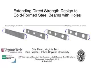
Comparison of buckling shapes Local buckling test 11.5Z092-1E2W Distortional buckling testD11.5Z092-3E4W
Comparison with U.S. Design Compared with North American Spec (NAS 2001) prediction 23 local buckling tests, average Mtest/MNAS=1.02 17 distortional buckling tests, average Mtest/MNAS=0.85
Distortional buckling tests only Compared with North American Spec (NAS 2001) prediction
Direct Strength Method vs. tests Local buckling tests Mtest/MDSL=1.03 Distortional buckling tests Mtest/MDSD=1.03* *formulas similar to AS/NZ Spec.
Extensions • Explicit DB check in North American Spec. • Restraint of existing systems? • Moment gradient influence on DB?
FEA result of local buckling test of Z beams h=8.5 in. t=0.12 in. Simulation @ 25% Imperfection P25%=17968.2 lbs (102.5% of test) Real test Ptest=17524.7 lbs Simulation @ 75% Imperfection P75%=16483.8 lbs (94.1% of test)
Conclusion • Tests that explicitly separate local and distortional buckling are necessary for understanding bending strength • Current North American Specifications are adequate only for local buckling limit states • The Direct Strength expressions work well for strength in local and distortional buckling • More work on restraint and influence of moment gradients is needed
Acknowledgments • Sponsors • MBMA and AISI • VP Buildings, Dietrich Design Group and Clark Steel • People • Sam Phillips - undergraduate RA • Tim Ruth - undergraduate RA • Jack Spangler – technician • James Kelley – technician
FE (elastic) and LB vs. DB single screw pattern, t=0.073 in. h=8.5 in. Z beam panels removed for visual purposes only paired screw pattern, t=0.073 in. h=8.5 in. Z beam panels removed for visual purposes only
Direct Strength Method Local buckling strength: Distortional buckling strength:
Local collapse mechanisms (a) Collapse of 8.5 in. Z, t=0.073 in. (b) Collapse of 8.5 in. Z, t=0.059 in. (c) Collapse of 8 in. C, t=0.097 in. (d) Collapse of 8 in. C, t=0.043 in.