Download
1 / 24
670 likes | 2.07k Views
Cold-Formed Steel History, Innovation and Design. Jon-Paul Cardin, P.E. JPCardin@SCAFCO.com. The History of Steel Framing Design. Use of cold-formed steel members started in both the United States and England in 1850’s

E N D
Cold-Formed Steel History, Innovation and Design Jon-Paul Cardin, P.E. JPCardin@SCAFCO.com
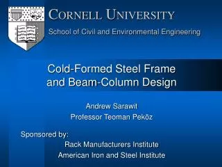
The History of Steel Framing Design • Use of cold-formed steel members started in both the United States and England in 1850’s • Although, use of steel framing limited up to the 1930 due to lack of design standards • 1939 American Iron and Steel Institute (AISI) sponsored a research project at Cornell University to develop specification for CFS • In 1946 the first Design Specification was published by AISI • The Specification has been updated and revised incrementally over the years • In 2001 the first NASPEC was published in coordination with Canada and Mexico
The History of Steel Stud Manufacturing • In the 1980’s every steel stud manufacturer had products with different dimensional profiles, steel thicknesses, and design specification catalog • Standard steel thickness was a Nominal thickness 0.0359” for 20 gaugewith tolerance of +/- 0.0030” (0.0329” – 0.0389”) • The tolerance was put in place because the steel mills could not guarantee minimum thicknesses during this time • By the end of the 1980’s the mill equipment was improved and the tolerances became tighter
The History of Steel Stud Manufacturing • 1990’s - Present • In the 1990’s manufacturers decided to standardize the steel framing industry by developing two manufacturing associations – one for the east coast and one for the west coast • In 1998, these two groups merge into the Steel Stud Manufacturing Association (SSMA) and standardizing the rest of the USA. • Currently, the SSMA, Steel Framing Industry Alliance (SFIA) and Certified Steel Stud Association (CSSA) are the three manufacturers associations
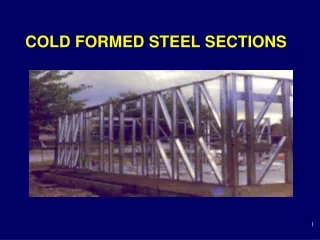
Benefits of Designing with Steel • Consistent material quality • Noncombustible • Dimensionally stable • No Rot • No Freeze/Thaw Effects • No Warp due to Moisture • Insect resistant • Flexibility in design • Lightweight • High strength-to-weight ratio • Most recycled material
Technical Catalogs • Member Section Properties • Allowable Span Tables • Interior Wall Heights • Composite • Non-Composite • Curtain Wall Heights • Combined Axial and Lateral • Floor Joist Spans • Ceiling Spans • Connection Capacity Tables
Composite Vs. Non-Composite Composite Wall Heights Non-Composite Wall Heights • Obtained from Testing at an accredited Laboratory. Tests are performed with drywall attached both sides full height. • Calculated assuming drywall attached both sides fully braced condition. The code does not allow us to take the strength of the drywall into account.
Composite Vs. Non-Composite Composite Wall Heights Non-Composite Wall Heights
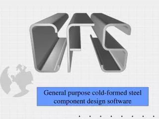
Design Software • CFS 8.0 - RGS Software • AISIWIN - Devco Software • LGBeamer – Devco Software • Other Proprietary Software
AISI Standards • North American Specification – NASPEC (S100) • Main Specification • Members, Assemblies, Systems, Connections • General Provisions (S200) • Floor and Roof System Design (S210) • Wall Stud Design (S211) • Header Design (S212) • Lateral Design (S213) • Truss Design (S214) • Prescriptive Method for One and Two Family Dwellings (S230) • CFS Design Manual (D-100) • Section Property Calculation Examples • Member Design Examples • CFS Design Guide (D-110) • Full System Design Examples
Design Considerations • Most failure modes of structural steel apply • In addition, CFS deals with thin/slender elements • Web Crippling • Local Buckling • Distortional Buckling • Flexural-Torsional Buckling • Utilize effective section properties • Web and Flange to Thickness Ratio Limitations for AISI Code Equations
Flexural Member Bracing • Flexural Members require bracing to resist torsion due to non-symmetric profile • Sheathing Both Sides • CRC Clipped to Stud • Flat Strap and Blocking • Sheathing One Flange with Rigid Bracing on Opposite Flange
Axial Member Bracing • Sheathing is not adequate for axial bracing • Bracing to resist both torsion and lateral displacement • Brace forces accumulate along stud wall at 2% of axial load, so the forces must be terminated to the structure or floor system
Axial Member Bracing • Brace forces must be terminated to the structure or floor system • Flat strap cross bracing (Figure 5) • Stud orientated in plane of the wall (Figure 6)
Web Stiffeners • Web stiffeners may be required at bearing locations due to web crippling • Web stiffeners required for h/t ratio between 200 and 260 • h = flat portion of web • Ratio tables available in catalogs • Catalogs and software specify when required due to loading • Back to back member typically adequate web stiffener • Clips at member ends (head of wall or base connections) or bypass locations considered web stiffeners
Innovation - High Strength Steel • In 2005, Dietrich puts UltraSteel on the market with the following characteristics: • Excessive knurling of the entire stud (dimpled) • Added a V-grove in the flanges • Increased steel yield strength from 33 ksi to 40 ksi • UltraSteel ended up NOT being a success, but it did open the door for the concept of engineered studs • The three characteristics that affect the strength of the stud: • Thickness • Profile • Grade/strength of steel
“EQ” Framing • Why is it called EQ? • EQ is an abbreviation for “equivalent” • The strength of steel studs used to be related to the thickness of the steel, but with the engineered studs, that is no longer the case • EQ means that the stud is manufactured with thinner material, but produces equivalent strength as the mentioned traditional stud • Example: 33EQS vs. 33mil
One and two piece pre-engineered systems available • Jamb is typically wide flange section • Clips connections from header to jamb studs Engineered Header and Jamb Systems
Member section properties available • Typically proprietary software available • Published allowable loads for clip connection Member and Connection Capacities
Test Ultimate Load and Serviceability Load (1/8”) • Reduction factor based on material tested • Safety factor based on test data reliability • Publish lower of serviceability and reduced ultimate load Published Capacities Based on Testing
Useful Links for CFS • Cold-Formed Steel Engineers Institute • www.cfsei.org • American Iron and Steel Institute (AISI) • www.steel.org • Wei-Wen Yu Center for Cold-Formed Steel Structures • www.ccfss.org
Thank You! Cold-Formed Steel History, Innovation and Design Jon-Paul Cardin, P.E. JPCardin@SCAFCO.com