Download
1 / 30
300 likes | 334 Views
Explore the world of logic gate families including Static CMOS, Complementary CMOS, and Dynamic Logic. Learn about the advantages and disadvantages of each type, as well as the implementation of compound gates and transmission gates. Dive into the details of pipeline structures in clockless computing.

E N D
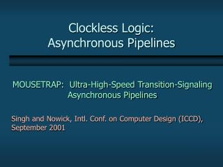
Clockless Computing Montek Singh Thu, Sep 6, 2007 Review: Logic Gate Families A classic asynchronous pipeline by Williams
Review:Logic Gate Families Static CMOS logic (“standard”) Transmission gates, or “pass-transistor” logic Dynamic logic, or “domino” logic
Static CMOS logic: Summary Advantages: • output always strongly driven • pull-up and pull-down networks are fully-complementary;always exactly one of them is “on” • good immunity from noise and leakage • both inverting and non-inverting functions implementable • each gate is inverting • cascade two gates together to get non-inverting logic Disadvantages: • slow/big PMOS devices needed (in addition to NMOS) • greater chip area • higher power consumption • slower switching speed
Complementary CMOS • Complementary CMOS logic gates • nMOS pull-down network • pMOS pull-up network • a.k.a. static CMOS OPTIONAL MATERIAL
Series and Parallel • nMOS: 1 = ON • pMOS: 0 = ON • Series: both must be ON • Parallel: either can be ON OPTIONAL MATERIAL
CMOS Gate Design • Activity: • Sketch a 4-input CMOS NOR gate OPTIONAL MATERIAL
CMOS Gate Design • Activity: • Sketch a 4-input CMOS NAND gate OPTIONAL MATERIAL
Conduction Complement • Complementary CMOS gates always produce 0 or 1 • Ex: NAND gate • Series nMOS: Y=0 when both inputs are 1 • Thus Y=1 when either input is 0 • Requires parallel pMOS • Rule of Conduction Complements • Pull-up network is complement of pull-down • Parallel -> series, series -> parallel OPTIONAL MATERIAL
Compound Gates • Compound gates can do any inverting function • Ex: OPTIONAL MATERIAL
Transmission (“Pass”) Gates Key Idea: • transistors used in a different configuration • when switched on: instead of connecting output to Vdd or Gnd, they connect output to the input Advantage: • very efficient for implementing switches and multiplexers Disadvantage: • signal degradation unless both NFET and PFET passgates are used in a complementary configuration
Pass Transistors • Transistors can be used as switches OPTIONAL MATERIAL
Pass Transistors • Transistors can be used as switches OPTIONAL MATERIAL
Transmission Gates • Single pass transistors produce degraded outputs • pMOS good only for transmitting “1” • nMOS good only for transmitting “0” OPTIONAL MATERIAL
Transmission Gates • Single pass transistors produce degraded outputs • Complementary Transmission gates pass both 0 and 1 well OPTIONAL MATERIAL
Multiplexers • 2:1 multiplexer chooses between two inputs OPTIONAL MATERIAL
Transmission Gate Mux • Nonrestoring mux uses two transmission gates • Only 4 transistors OPTIONAL MATERIAL
Gate-Level Mux Design • How many transistors are needed? 20 OPTIONAL MATERIAL
Dynamic Logic, or “domino” Key idea: • only use NMOS’s to compute function • use a single PMOS to reset Advantages: • significantly fewer transistors smaller chip area • higher speed, lower power • less “loading” on wires (drive fewer transistors) • for async: no storage elements needed Disadvantages: • need extra control input to precharge • logic is typically non-inverting only • more vulnerable to noise and leakage effects
Dynamic Logic, or “domino” (contd.) Gate has 2 phases: • precharge (=reset): output reset to ‘0’ • evaluate: output computed either stays ‘0’, or switches to ‘1’ Pull-up and pull-down must never both be simultaneously active: • ensure that data inputs are reset while gate is precharging • or, add a “footer” device control input controls“precharge” PC PC =0 (asserted) precharge pull-upnetwork pull-down network dataoutput PC =1 (de-asserted) evaluate datainputs controls“evaluation”
Outline: Several Pipeline Styles • Classic static logic pipeline: Sutherland • Recent static logic pipeline: MOUSETRAP • Classic dynamic logic pipeline: Williams/Horowitz’ PS0
A Classic AsynchronousDynamic Pipeline Williams and Horowitz’s PS0 pipeline: Structure Operation Performance
A Classic Approach: PS0 Pipeline Stage 2 Stage 3 Stage 1 ack Data in Data out data Processing Block Completion Detector Williams/Horowitz (Stanford U.) [1986-91]: • successfully used in fabricated chips [Stanford ’87] [HAL ’90s] Implemented using “dynamic logic”
PS0 Pipeline Stage ack Completion Detector A PS0 stage consists of dynamic gates and a completion detector: PC “keeper” datainputs Pull-down network dataoutputs Processing Block
Dual-Rail Completion Detector bit0 bitn bit1 OR OR OR Done C • Combines dual-rail signals • Indicates when all bits are valid (or reset) C-element: • if all inputs=1, output 1 • if all inputs=0, output 0 • else, maintain output value • OR together 2 rails per bit • Merge results using “C-element”
PS0 Protocol 4 3 indicates “done” 6 5 1 2 3 • PRECHARGE N: when N+1 completes evaluation • delete data:after next stage has copied it • EVALUATE N: when N+1 completes precharging • accept new data: after next stage is emptied indicates “done” indicates “done” N N+1 N+2 precharges evaluates evaluates evaluates Complete cycle: 6 events Evaluate Precharge: 3 events Precharge Evaluate: another 3 events
PS0 Performance 6 4 Cycle Time = 5 1 2 3
Summary: PS0 Pipelining Datapaths are latch-free: • dynamic gates themselves provide implicit latches +: chip area savings +: extremely low latency Data items kept separate by control • stage deletes data:only afternext stage has copied it • stage accepts new data:only ifnext stage is empty • distinct data items always separated by “spacers” Control is extremely simple: each controller = single wire • completion detector directly controls previous stage +: chip area savings +: low control overhead
Comparison to a Clocked Pipeline latch How would you design the pipeline if you actually had a clock? • Replace handshaking with “magic clocking” • each stage gets its own clock • successive clocks are slightly skewed • essentially, clocked simulation of asynchronous handshaking! – need multiple clock phases! • Use a single clock, but insert latches between stages • latches are simple, level-sensitive • consecutive stages receive complementary clock signals Ck Ck’
Drawbacks of PS0 Pipelining • Poor throughput: • long cycle time: 6 events per cycle • data “tokens” are forced far apart in time • Limited storage capacity: • max only 50% of stages can hold distinct tokens • data tokens must be separated by at least one spacer My Research Goals have been: address both issues • still maintain very low latency
Homework #4 (due Tue Sep 18) • Enumerate ALL of the timing assumptions inherent in Williams’ PS0 style • Assume all gate and wire delays can be arbitrary • For which scenarios can there be a malfunction? • Compare the cycle times of PS0 with an ideal clocked dynamic pipeline (slide #28)