Download
1 / 11
110 likes | 146 Views
This article discusses the need for redesigning the RFQ for a 50MV/m field enhancement factor, aiming to improve acceleration efficiency and transverse acceptance. It compares measured emittance and RFQ acceptance, explores the benefits of a higher field, and explains the use of an acceptance mask for validation.

E N D
Alessandra Lombardi Jean-Baptiste Lallement Daniel Noll RFQ LINAC4 redesign Why did we ask for 50MV/m?
The problem Comparison of measured emittance (yellow) and RFQ acceptance (pink). The expected transmission thru the RFQ is 75%. (PARMTEQ + TOUTATIS) Average current during the last measurement campaign : 40 mA IEFC 6 feb 2015 - AL
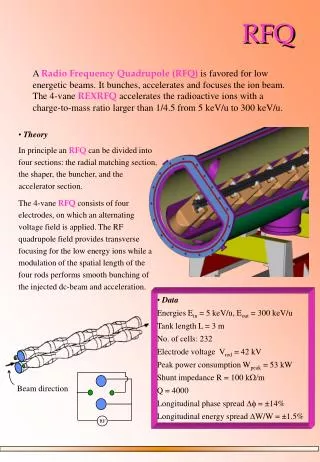
The RFQ today – more from Carlo in a momentfrom note L4RFQ_ES_26062009 The maximum field on the vane-tip is an input to the design. Then We try to minimise with an appropriate transverse radius of curvature we balance between transverse acceptance and efficiency of acceleration (modulation factor)
R0 and rho –already played that card 2R0 = average distance between opposite vanes rho : Transverse radius of curvature of the vane-tip. Looking in from the RF port : these are adjacent vanes Beam goes into the paper in between the 4 vanetips
Why a high field would be beneficial - • Lets look at the “field enhancement factor” vs cell length and modulation for the case of LINAC4 (applies to all RFQ)
typical emittance plot- these are measurements This is in one plane. Example: For the highlighted dot we have 50% in the RFQ acceptance (0.7*0.7)
How much do we gain 50MV/m this is where we want to be 36MV/m this is where we are
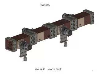
Test stand is equipped with rfq acceptance mask-validated Rfq acceptance mask : four intercepting plates with squared aperture restrictions. The aperture size and their relative distances are chosen such that only the particles within the RFQ acceptance can pass through all four aperture restrictions.