Download

1 / 37
370 likes | 427 Views
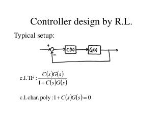
Lead Controller Design. p lead. z lead. 20log(Kz lead /p lead ). Goal: select z and p so that max phase lead is at desired wgc and max phase lead = PM defficiency !. Lead Design . From specs => PM d and w gcd From plant, draw Bode plot

E N D
plead zlead 20log(Kzlead/plead) Goal: select z and p so that max phase lead is at desired wgc and max phase lead = PM defficiency!
Lead Design • From specs => PMd and wgcd • From plant, draw Bode plot • Find PMhave = 180 + angle(G(jwgcd) • DPM = PMd - PMhave + a few degrees • Choose a=plead/zlead so that fmax = DPM and it happens at wgcd
Lead Design Variation • There is ess and Mp requirement • From ess_d, compute K = ess/ess_d • Draw Bode plot of KG, find PM & wgc • From Mp specs, find PMd • fmax = DPM = PMd - PMhave + extraextra
Lead design example • Plant transfer function is given by: • n=[50]; d=[1/5 1 0]; • Desired design specifications are: • Step response overshoot <= 20% • Ess to unit ramp <= 1/200; • G is type 1, Kv = 50/1=50 • Need to be increased by 4 x
n=[50]; d=[1/5 1 0]; figure(1); clf; margin(n,d); grid; hold on; ess2ramp= 1/200; Kvd=1/ess2ramp; Kva = n(end)/d(end-1); Kzp = Kvd/Kva; figure(2); margin(Kzp*n,d); grid; [GM,PM,wpc,wgc]=margin(Kzp*n,d); w_gcd=wgc; Mp = 20/100; zeta =sqrt((log(Mp))^2/(pi^2+(log(Mp))^2)); PMd = zeta * 100 + 10; phimax = (PMd-PM)*pi/180; alpha=(1+sin(phimax))/(1-sin(phimax)); z=w_gcd/sqrt(alpha); p=w_gcd*sqrt(alpha); ngc = conv(n, alpha*Kzp*[1 z]); dgc = conv(d, [1 p]); figure(3); margin(tf(ngc,dgc)); grid; [ncl,dcl]=feedback(ngc,dgc,1,1); figure(4); step(ncl,dcl); grid; figure(5); margin(ncl*1.414,dcl); grid;
Problem • wgc moved to a new location • At a higher frequency • Phi_max was not at actual wgc • PM at actual wgc is too small • Solution: • Anticipate this upward wgc change • Place both z_lead and p_lead at a higher frequency than original wgc
n=[50]; d=[1/5 1 0]; figure(1); clf; margin(n,d); grid; hold on; ess2ramp= 1/200; Kvd=1/ess2ramp; Kva = n(end)/d(end-1); Kzp = Kvd/Kva; figure(2); margin(Kzp*n,d); grid; [GM,PM,wpc,wgc]=margin(Kzp*n,d); w_gcd=wgc; Mp = 20/100; zeta =sqrt((log(Mp))^2/(pi^2+(log(Mp))^2)); PMd = zeta * 100 + 10; phimax = (PMd-PM)*pi/180; alpha=(1+sin(phimax))/(1-sin(phimax)); z=w_gcd/alpha^.25; %sqrt(alpha); p=w_gcd*alpha^.75; %sqrt(alpha); ngc = conv(n, alpha*Kzp*[1 z]); dgc = conv(d, [1 p]); figure(3); margin(tf(ngc,dgc)); grid; [ncl,dcl]=feedback(ngc,dgc,1,1); figure(4); step(ncl,dcl); grid; figure(5); margin(ncl*1.414,dcl); grid;
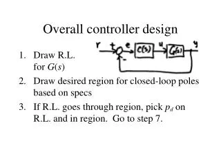
Lead design tuning example C(s) G(s) Design specifications: rise time <=2 sec overshoot <16%
Desired tr < 2 sec We had tr = 1.14 in the previous 4 designs 4. Go back and take wgcd = 0.6*wn so that tr is not too small
n=[1]; d=[1 5 0 0]; G=tf(n,d); Mp_d = 16/100; zeta_d =0.5; % or calculate from Mp_d PMd = 100*zeta_d + 10; tr_d = 2; wnd = 1.8/tr_d; w_gcd = 0.6*wnd; Gwgc=evalfr(G, j*w_gcd); PM = pi+angle(Gwgc); phimax= PMd*pi/180-PM; alpha=(1+sin(phimax))/(1-sin(phimax)); zlead= w_gcd/sqrt(alpha); plead=w_gcd*sqrt(alpha); K=sqrt(alpha)/abs(Gwgc); ngc = conv(n, K*[1 zlead]); dgc = conv(d, [1 plead]); [ncl,dcl]=feedback(ngc,dgc,1,1); stepchar(ncl,dcl); grid figure(2); margin(G); hold on; margin(ngc,dgc); hold off; grid