Download
1 / 29
290 likes | 413 Views
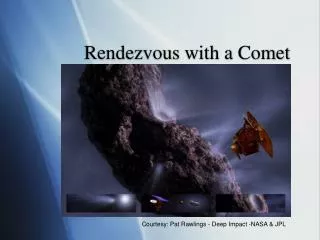
Comet Ephemerides with Geometry and Visibility Info. by Steve Albers. DEC, RA, Distance from Sun and Earth Magnitude, Tail Length, Tail orientation Phase Angle, Elongation Rise/Set Times, Time/Altitude for best viewing Visibility compared to naked eye, binocular thresholds

E N D
Comet Ephemerides with Geometry and Visibility Info by Steve Albers
DEC, RA, Distance from Sun and Earth • Magnitude, Tail Length, Tail orientation • Phase Angle, Elongation • Rise/Set Times, Time/Altitude for best viewing • Visibility compared to naked eye, binocular thresholds • expressed as “effective” or corrected magnitude • Output computed daily or more frequently Ephemeris Output
Effective Magnitude Adjusted from Actual Magnitude • compare to naked eye 6.0 threshold • Effective Magnitude Adjustments • extinction • sky brightness (moonlight, twilight, daylight at best observation time) Visibility Computation
Nighttime • moderate light pollution assumed, increasing near horizon • increased by scattering/glare from the moon • Twilight • empirical relationship of limiting magnitude and comet/sun altitude difference • Daytime • scattering/glare based on elongation from sun, comet altitude and solar altitude Sky Brightness Computation
Internet Demo? http://laps.noaa.gov/cgi/albers.homepage.cgi (optional)
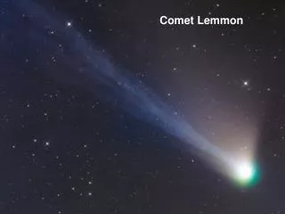
PANSTAARS reaching (barely) naked eye magnitude limit in March PANSTAARS reaching (barely) naked eye magnitude limit in March • Ikeya-Seki visible naked eye in Japan within hours of perihelion, otherwise head was likely invisible naked-eye (despite impressive tail) • ISON orbit similar to Ikeya-Seki, though will be dimmer and may never reach naked-eye brightness • Hale-Bopp longest most visible comet in last 50 years • McNaught (2007) visible naked eye from Longmont area in bright twilight, and in binoculars during the daylight Visibility Examples
Sky Brightness Computation • It’s fine to calculate sky brightness and limiting magnitude at individual points in the sky for an ephemeris, however… • Wouldn’t it be nice to show an image of sky brightness over the entire sky??
Simulated All-Sky Images Compared with the LAS All-Sky Camera by Steve Albers, Vern Raben, and the NOAA LAPS Group
3-D Gridded Cloud Analyses (or forecasts) • Cloud liquid, ice, rain, snow,hail • NOAA’s LAPS model (developed at ESRL) • Locations of Sun, Moon, Planets, Stars • Specification of Aerosols (haze) • Specification of Light Pollution • Specify Vantage Point • Latitude, Longitude, Elevation Simulation Ingredients
LAPS Cloud analysis First Guess METAR METAR METAR OAR/ESRL/GSD/Forecast Applications Branch 10
Illumination of clouds, air, and terrain are pre-computed • Sky brightness based on sun, moon, planets, stars • Ray Tracing from Vantage Point to each sky location • Scattering by Intervening Clouds, Aerosols, Air • Terrain shown where its along the line of sight • Physically and Empirically based for best efficiency Visualization Technique
Overall correction based on optical axis centering, spherical rotation, and radial lens “distortion” Image Navigation • Need to rotate around Lambda Draconis? • Except that near horizon offsets are just in azimuth (zenith rotation)
Cloud Illumination (and scattering) Cloud Illumination Example
Source can be sun or moon • Rayleigh Scattering by Air Molecules (blue sky) • Minimum brightness 90 degrees from light source • Blue-Green sky color near horizon far from sun • Mie Scattering by Aerosols (haze) • Brighter near the light source (aureole) • Added sky brightness from planets, stars, light pollution, airglow Background Sky Brightness
Cloud shadows in clear air can show crepuscular rays • Brightness and color changes shown during twilight • 3-D orientation of Earth’s shadow considered • Secondary scattering needed to reduce contrast in Earth’s shadow that appears opposite the sun Clear Air Illumination
Topography data allows showing mountains near the horizon • Terrain Albedo (e.g. a dark forest) • Adjusted by cloud shadows • Show snow cover (future enhancement) • Terrain can be obscured by intervening clouds, haze, or clear air (very long distances) Terrain Illumination
Trace from viewer into sky at ~1x1 degree grid • Ray path travels through clear air, aerosols, clouds, and may hit terrain • First estimate is clear sky value (background sky) • Scattered by clouds (can show up either bright or dark) • depends on optical depth of cloud and elongation from sun, as well as pre-computed cloud illumination • Cloud/Aerosol scattering can obscure distant terrain Main Ray-Tracing Step
Mie scattering phase function means thin clouds are brighter near the sun (silver lining), cloud corona • Thick clouds are the opposite, being lit up better when opposite the sun • Rayleigh scattering by clear air can redden distant clouds • Future enhancement would be to add rainbows & halos • (with clouds/precip at specific elongation angles) More on Cloud/Precip Scattering
Cylindrical grid (panoramic view) can be calculated at either 1x1 or 0.5x0.5 degree spacing • Currently just shows at and above the horizon • future enhancement to show below the horizon • Convert to polar grid (shown here) • good for overhead views, and for camera comparison Final Display
Cylindrical Panoramic View (½ degree resolution)
Internet Demo of All-sky Web page? (optional) http://laps.noaa.gov/allsky/allsky.cgi
What’s next? The sky is the limit!