Download
1 / 55
550 likes | 592 Views
Discover the fundamentals of sequential logic circuits, including latches, flip-flops, and related devices. Study the different types of logic elements, such as bistable, monostable, and astable devices, and understand their applications in memory and storage. Learn about synchronous and asynchronous logic design and explore examples of edge-triggered flip-flops. Dive into the functionalities of S-R latches, gated S-R latches, and gated D latches. Enhance your knowledge of sequential logic devices for efficient circuit design.

E N D
Sequential LogicFlip-Flops andRelated Devices Dr. Rebhi S. Baraka rbaraka@iugaza.edu.ps Logic Design (CSCI 2301) Department of Computer Science Faculty of Information Technology The Islamic University of Gaza
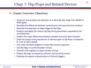
Outline • Basic Definitions • Latches • Edge-Triggered Flip-Flops • Master-Slave Flip-Flops
What is Sequential Logic • Sequential logic is a type of logic circuit whose output depends not only on the present input but also on the history of the input. • The basic memory element in sequential logic is the Flip-Flop. Outputs Inputs Combinational circuit Memory elements
Types of Sequential Logic • Synchronous logic or clocked logic : there is a clock signal, and the internal memory changes only on a clock edge. Combinational circuit Outputs Inputs Memory elements Clock pulses
Types of Sequential Logic • Asynchronous logic: The behavior of the circuit depends upon the input signals at any instant of time and the order in which the inputs change. The storage elements used are time-delay devices, i.e. the time it takes for the signal to propagate through the device.
sequential Logic Devices (Multivibrators) • Bistable: bistable devices have two stable states, called SET and RESET. • Monostable: monostable devices (one shot) have only one stable state. • Astable: astable devices have no stable state and used as oscillator.
Bistable Devices • Bistable devices have two stable states, called SET and RESET. • They can retain either of these states indefinitely, making them useful as storage devices. • Two categories of bistable devices: • The Latch • The Flip-Flop The basic difference between latches and flip-flops is the way in which they are changed from one state to the other.
Latches • The latch is a bistable device that can reside in either of two states by means of a feedback arrangement. • The main difference between a latch and a flip-flop is in the method used for changing their state. • Latches operate with signal levels making. We study: • S-R (Set-Reset) latch • Gated S-R latch • Gated D latch
S-R Latch • An active-HIGH input S-R (Set-Reset) latch is formed with two cross-coupled NOR gates as shown below
S-R Latch The function table of an active-HIGH input S-R latch summarizes its operation.
Latch • An active-LOW input (Set-Reset) latch is formed with two cross-coupled NAND gates (respectively negative-OR gate ).
Latch The function table of an active-LOW input latch summarizes its operation.
The three modes of operation (SET, RESET, no-change) and the invalid state
Example: If the S’ and R’ waveforms are applied to the inputs of the active-Low S’-R’ latch, determine the waveform that will be observed on the Q output. Assume that Q is initially LOW.
The gated S-R latch • A gated latch requires an enable input, EN (as show in the next slide). • The S and R inputs control the state to which the latch will go when a HIGH level is applied to the EN input. • The latch will not change until EN is HIGH, but as long as it remains HIGH, the output is controlled by the state of the S and R inputs. • The invalid state occurs when both S and R are simultaneously HIGH.
Determine the Q waveform if the inputs are applied to the gated S-R latch that is initially RESET. Example:
The gated D Latch • It differs from the S-R latch in having only one input in addition to EN. • This input is called the D (data) input (see next slide). • When the D input is HIGH and the EN input is HIGH, the latch will set. • When the D input is LOW and the EN input is HIGH, the latch will reset. • The output Q follows the input D when En is HIGH.
Flip-Flops • Flip-Flops are synchronous bistable devices • Synchronous means that the output changes state only at a specified point on a clock (CLK). • The clock is designated as a control input C. • We study two types of flip-flops: • Edge-Triggered Flip-Flops • Master-Slave Flip-Flops
Edge-Triggered Flip-Flops • An Edge-Triggered Flip-Flop changes state either at the positive edge (rising edge) or at the negative edge (falling edge) of the clock pulse. • Three types: • S-R Edge-Triggered Flip-Flop. • D Edge-Triggered Flip-Flop. • J-K Edge-Triggered Flip-Flop.
S-R Edge-Triggered Flip-Flops • S and R inputs here are called synchronous inputs because data on these inputs are transferred to the output only on the triggering edge of the clock pulse. • When S is HIGH and R is LOW, the Q output goes HIGH on the triggering edge of the clock pulse, and the flip-flop is set. • When S is LOW and R is HIGH, the Q output goes LOW on the triggering edge of the clock pulse, and the flip-flop is reset. • When both S and R are LOW, the output does not change. • When both S and R are HIGH, an invalid condition exists.
S-R Edge-Triggered Flip-Flop Logic Symbol Function (truth) Table
Method of Edge-Triggering • The pulse transition detector produces a very short duration spike (of few nanoseconds) on the positive-going transition of the clock pulse. • This is caused by the small delay on one input to the NAND gate.
Flip-flop making a transition from the RESET state to the SET state on the positive-going edge of the clock pulse.
Flip-flop making a transition from the SET state to the RESET state on the positive-going edge of the clock pulse.
Edge-triggered D flip-flop • The D flip-flops is useful when a single bit is to be stored.
Edge-triggered D flip-flop Given the waveforms for the D and the clock, determine the Q output waveform if the flip-flop starts out RTESET.
Edge-triggered J-K flip-flop • The J-K flip-flop differs in that it has no invalid state. • This is achieved by the connecting Q output to Gate 2 and connecting Q’ to Gate 1 as shown below
Edge-triggered J-K flip-flop Given the waveforms for the J, K and the clock. Determine the Q output waveform if the flip-flop starts out RTESET.
Edge-triggered J-K flip-flop Given the waveforms for the J, K and the clock. Determine the Q output waveform if the flip-flop starts out RTESET.
Asynchronous Preset and Clear Inputs • These are inputs that affect the state of the flip-flop independent of the clock. • They are labeled preset (PRE) and clear (CLR), or direct set (SD) and direct reset (RD)
Asynchronous Preset and Clear Inputs (Logic Diagram) for the J-K Flip-Flops • Active LOW preset (PRE) and clear (CLR) inputs. • The inputs are connected so that they override the effect of the synchronous inputs, J, K, and the clock.
Master-Slave Flip-Flops • In this kind of flip-flops data are entered into the flip-flop at the leading at the leading edge of he clock pulses, but the output does not reflect the input state until the trailing edge. • The pulse-triggered master-slave flip-flop does not allow data to change while the clock pulse is active.
The Pulse-Triggered Master-Slave J-K Flip-Flop • It is composed of two sections: • The master section which is a gated latch • The Slave section which is a gated latch clocked on the inverted clock pulse and is controlled by the outputs of the master section • The master section responds to the J and K inputs at the leading edge of the clock • The slave section responds to the Q and Q’ of the master section of the trailing edge of the clock.
Flip-Flop Operating Characteristics Self study! • Propagation delay times • Set-up time • Hold time • Maximum clock frequency • Pulse widths • Power dissipation
Flip-Flop Applications • Parallel data storage • Frequency division • Counting
Flip-Flop Applications: parallel data storage • Store several bits of data from parallel lines simultaneously in a group of flip-flops. • As shown in the next slide, the asynchronous reset (R) inputs are connected to a common CLR line, which initially resets all the flip-flops. • This is an example of a basic register used for data storage.
Flip-Flop Applications: Frequency division • Dividing (reducing) the frequency of a periodic waveform. • When a pulse waveform is applied to the clock input of the J-K flip-flop with a toggle mode, the Q output is a square wave with one-half the frequency of the clock input. • Thus, a single flip-flop can be applied as a divide-by-2 device, i.e., resulting in an output that changes at half the frequency of the clock waveform.
The J-K flip-flop as a divide-by-2 device. Q is one-half the frequency of CLK.
Example of two J-K flip-flops used to divide the clock frequency by 4. QA is one-half and QB is one-fourth the frequency of CLK.
Example: Develop the fout waveform for the given circuit when an 8 KHz square wave input is applied to the clock input of the flip-flop.