Download
1 / 75
750 likes | 795 Views
Explore the challenges and benefits of designing asynchronous circuits, emphasizing on automation in designing correct and efficient asynchronous circuits. Learn about synthesis flow, reachability analysis, state graph, logic decomposition, technology mapping, and more.

E N D
Automatic synthesis and verification of asynchronous interface controllers Jordi Cortadella Universitat Politècnica de Catalunya, Spain Michael Kishinevsky Intel Corporation, USA Alex Kondratyev Theseus Logic, USA Luciano Lavagno Università di Udine, Italy Enric Pastor Universitat Politècnica de Catalunya, Spain Marco A. Peña Universitat Politècnica de Catalunya, Spain Alexander Yakovlev University of Newcastle upon Tyne, UK
y- a- a+ b+ x- y+ c x+ y+ b- a c+ x+ y- x- c- b y x Specification(environment) Implementation (circuit)
Why and why not? • Asynchronous circuits: robustness, modularity, less power consumption, low EMI, no clock skew and many other debatable advantages • Designing correct async circuits is difficult(hazards, testing) • Designing efficient async circuits is a nightmare (time comes into play) • Design automation is crucial
Outline • Synthesis flow with STGs • Specification • State graph and next-state functions • State encoding • Implementability conditions • Logic decomposition • Synthesis with relative timing assumptions • Formal verification of timed circuits
Specification(STG) Reachability analysis State Graph State encoding SG withCSC Design flow Boolean minimization Next-state functions Logic decomposition Decomposed functions Technology mapping Gate netlist
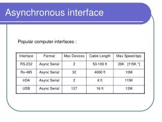
Bus Data Transceiver DSr LDS Device D LDTACK DSr LDS VME Bus Controller DSw LDTACK D DTACK DTACK Read Cycle VME bus
STG for the READ cycle DSr+ DTACK- LDS+ LDTACK+ D+ DTACK+ DSr- D- LDTACK- LDS- D LDS DSr VME Bus Controller LDTACK DTACK
Specification(STG) Reachability analysis State Graph State encoding SG withCSC Design flow Boolean minimization Next-state functions Logic decomposition Decomposed functions Technology mapping Gate netlist
LDS + LDS = 0 LDS - LDS = 1 Binary encoding of signals DSr+ DTACK- LDS+ LDTACK- LDTACK- LDTACK- DSr+ DTACK- LDS- LDS- LDS- LDTACK+ DSr+ DTACK- D+ D- DTACK+ DSr-
01100 00110 State graph 10000 DSr+ DTACK- LDS+ LDTACK- LDTACK- LDTACK- DSr+ DTACK- 10010 LDS- LDS- LDS- LDTACK+ DSr+ DTACK- 10110 01110 10110 D+ D- DTACK+ DSr- (DSr , DTACK , LDTACK , LDS , D)
ER (LDS+) LDS+ QR (LDS-) LDS- LDS- LDS- ER (LDS-) QR (LDS+) Excitation / Quiescent Regions
LDS+ LDS- LDS- LDS- 10110 10110 Next-state function 0 1 0 0 1 1 1 0
DTACK DSr DTACK DSr D LDTACK D LDTACK 00 00 01 01 11 11 10 10 00 00 01 01 11 11 10 10 Karnaugh map for LDS LDS = 1 LDS = 0 - - - 0 0 - 1 1 - - - - - - - - 1 1 1 - - - - - 0 0 - 0 0 0 - 0/1?
Specification(STG) Reachability analysis State Graph State encoding SG withCSC Design flow Boolean minimization Next-state functions Logic decomposition Decomposed functions Technology mapping Gate netlist
DSr+ DSr+ DSr+ Concurrency reduction LDS+ LDS- LDS- LDS- 10110 10110
Concurrency reduction DSr+ DTACK- LDS+ LDTACK+ D+ DTACK+ DSr- D- LDTACK- LDS-
State encoding conflicts LDS+ LDTACK- LDS- LDTACK+ 10110 10110
CSC+ CSC- Signal Insertion LDS+ LDTACK- LDS- LDTACK+ 101101 101100 D- DSr-
Specification(STG) Reachability analysis State Graph State encoding SG withCSC Design flow Boolean minimization Next-state functions Logic decomposition Decomposed functions Technology mapping Gate netlist
Implementability conditions • Consistency + CSC + persistency • There exists a speed-independent circuit that implements the behavior of the STG(under the assumption that ay Boolean function can be implemented with one complex gate)
Specification(STG) Reachability analysis State Graph State encoding SG withCSC Design flow Boolean minimization Next-state functions Logic decomposition Decomposed functions Technology mapping Gate netlist
No Hazards abcx 1000 b+ 1 1 0 0 a 1100 x 1 1 0 1 0 b a- c 0 0 0 1 0100 c+ 0110
abcx 1000 1 0 b+ a z 0 0 1100 b x c a- 0 0100 1 0 0 1 0 1 1 0 1 0 c+ 1 1 1 1 1 0 0 0 1 0 0110 0 0 0 1 1 Decomposition May Lead to Hazards 1000 1100 1100 0100 0110
y- y- 1001 1011 z- w- 1000 0001 w+ y+ w- z- x+ z- w- w+ 1010 0000 0101 0011 w- y+ x+ z- y+ x+ x- 0010 0100 x- x+ y+ z+ 0110 0111 z+ Decomposition example
y- 1001 1011 z- w- 1000 0001 w+ y+ w- z- x+ 1010 0000 0101 0011 w- y+ x+ z- C 0010 0100 x- x+ y+ z+ C 0110 0111 yz=0 yz=1 x y- y w 1001 1011 z- z w- y 1000 0001 w+ y+ z w- z- x+ x w 1010 0000 0101 0011 w- y+ x+ z- w z y 0010 0100 x- z x+ y+ z+ y 0110 0111 x z y
C C s=1 x y- w s 1001 1011 y z- s- z w+ 1001 1000 z- s- y+ w- x w 0011 1000 0001 1010 y+ s- w- z- x+ w x- z y 1010 0000 0101 z w- y+ x+ z- 0111 0010 0100 y s+ x+ y+ x z s=0 z+ 0111 y 0110
s=1 y- y- 1001 1011 z- s- s- w+ 1001 1000 z- s- y+ w- z- w- w+ 0011 1000 0001 1010 y+ s- w- z- x+ x- 1010 0000 0101 y+ x+ x- w- y+ x+ z- 0111 0010 0100 s+ s+ x+ y+ z+ s=0 z+ 0111 0110
Adding timing assumptions DSr+ DTACK- LDS+ LDTACK+ D+ DTACK+ DSr- D- LDTACK- LDS- D DTACK LDS map csc DSr LDTACK
Bus Data Transceiver Device D LDS DSr VME Bus Controller LDTACK DTACK D DTACK LDS map csc DSr LDTACK
LDTACK- before DSr+ SLOW FAST Adding timing assumptions DSr+ DTACK- LDS+ LDTACK+ D+ DTACK+ DSr- D- LDTACK- LDS- D DTACK LDS map csc DSr LDTACK
LDTACK- before DSr+ Adding timing assumptions DSr+ DTACK- LDS+ LDTACK+ D+ DTACK+ DSr- D- LDTACK- LDS- D DTACK LDS map csc DSr LDTACK
LDTACK- before DSr+ State space domain DSr+ LDTACK-
LDTACK- before DSr+ State space domain DSr+ LDTACK-
LDTACK- before DSr+ State space domain DSr+ LDTACK- Two more unreachable states
DTACK DSr DTACK DSr D LDTACK D LDTACK 00 00 01 01 11 11 10 10 00 00 01 01 11 11 10 10 Boolean domain LDS = 1 LDS = 0 - - - 0 0 - 1 1 - - - - - - - - 1 1 1 - - - - - 0 0 - 0 0 0 - 0/1?
DTACK DSr DTACK DSr D LDTACK D LDTACK 00 00 01 01 11 11 10 10 00 00 01 01 11 11 10 10 Boolean domain LDS = 1 LDS = 0 - - - 0 0 - 1 1 - - - - - - - - 1 1 1 - - - - - 0 0 - - 0 0 - 1 One more DC vector for all signals One state conflict is removed
Netlist with one timing constraint DSr+ DTACK- LDS+ LDTACK+ D+ DTACK+ DSr- D- LDTACK- LDS- D DTACK LDS map csc DSr LDTACK
D DTACK TIMING CONSTRAINT LDTACK- before DSr+ LDS DSr LDTACK Netlist with one timing constraint DSr+ DTACK- LDS+ LDTACK+ D+ DTACK+ DSr- D- LDTACK- LDS-
Types of timing assumptions • Environment slower (or faster) than the circuit • Gate delay shorter than another gate delay • Speculative enabling (events enabled beforethey must actually occur) • Indistiguishable firing times of different events • . . .
Formal verification • Implementability properties • Consistency, persistency, state coding … • Behavioral properties (safeness, liveness) • Mutual exclusion, “ack” after “req”, … • Equivalence checking • Circuit Specification • Circuit < Specification
x • Property • g must fire before d after having fired x a b b g a c c g b c a b c g c b d g y d g
Verifying asynchronous circuits • Internal signals cannot be abstracted out(many more state signals and states) • If delays must be taken into account, each gate is a component with delay • Verification with timed automata results unmanageable (BDDs do not work):Gate = counter + state signal • We need clever strategies to do symbolic model checking
x • Timed Transition System • (Manna, Pnueli) • Transition System • Min/Max Delays a b b g a c c b c c g d(a) [1,2] d(b) [1,2] d(c) [2.5,3] d(g) [0.5,0.5] d(d,x,y) [0,) c y d
{x} x {a,b} a {b,c,g} b {c,g} c {d,g} d {g} g Ø x a b b g a c c g b c a b c g c b d g y d g
{x} x x {a,b} a {b,c,g} a b b {c,g} c g c {d,g} d {g} d g Ø x x a b a g c b c d d g
0 3.5 0 2.5 -1.5 0 longest min path for d slack for max path of g -2 0 0 0 0 0 Maximum Time Separation (McMillan & Dill, 1992) x [1,2] [1,2] a b [0.5,0.5] [2.5,3] g c [0,) [0,) d max t(g) - t(d) = -2
Maximum Time Separation (McMillan & Dill, 1992) x From absolute to relative timing a b g c d max t(g) - t(d) = -2
x x a b a b b g a c c g c g b c a b c g d c b d g y d g