Download
1 / 37
370 likes | 380 Views
Detailed analysis of optical instrument upgrades and alignment methods for optimal performance and accuracy. Includes developments in feedback systems and precision components.

E N D
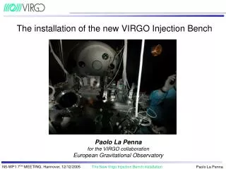
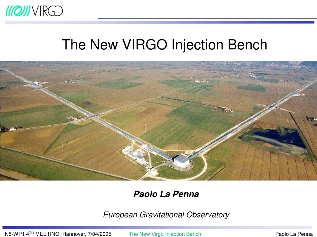
The New VIRGO Injection Bench Paolo La Penna European Gravitational Observatory
PR REFLECTION INSIDE IMC: FREQUENCY NOISE Black: PR misaligned Red: PR aligned
PR reflection scattering inside IMC MC scattering (10 ppm) IMC PR Cavity effect (10% fringes)
Simulations on a lock acquisition technique developed following the LIGO experience Locking trials with this baseline technique failed (first half of July) Attenuator installed (summer) Restart of the locking trials with the baseline technique (21st September) Establishement of theVariable Finesse lock acquisition technique (October) PR cavity locking (end of October) The PR feedback inside the IMC (Summer 2004 - now)
Temporary solution: Input Beam Attenuation IMC 10% M6 From the laser To the interferometer 700 mW (10% of the full power) Reference Cavity Final solution: Insert a Faraday Isolator
OLD M6 vs NEW M6 OLD M6 (Same y-scale) NEW M6 Hz Hz PR LOCKING ACQUIRED AFTER ONE MONTH CONFIRMATION OF THE BACKSCATTERING PROBLEM NEED OF AN ISOLATOR (FARADAY)
Beam diameter 10 mm Beam waist 5mm If a Faraday is needed it will have a large aperture
TGG (Terbium Gallium Garnet,) vacuum compatible; 20 mm maximum clear aperture : (25 and 50 mm would be “glass based” rotators, not reliable for 10 W power); Weight: 7 kg, TGG rod length: 20 mm, isolator length: 25 cm Extinction measured in Nice 41 db; Absorption: less than 0.0025 cm-1; EOTec uses vacuum compatible thin film polarizers at Brewsters angle: BK7 Pulsed damage threshold >5J/cm2 10nsec pulse Extinction >1000:1 @1064 nm Transmission: 95-97% @1064 nm (97% maximum) EOTec Faraday Isolator
Faraday isolator: present bench 670 mm 250 mm Not enough space on the present bench
Even with a 20 mm clear aperture Faraday: The IMC waist is 5 mm: the beam has to be reduced in size before entering in the Faraday A telescope for reducing the beam to 2-3 mm in the Faraday has to be taken into account and designed Thermal lensing: no plan to correct it (using FK51 for example) with present input power (about 10 W): the induced focal length should be of the order of 50-100 m Induced (stationary) thermal lensing effects will be corrected acting on the matching telescope. IB design with a Faraday Isolator
Faraday Isolator Brewster dielectric polarizers Rotator
Thermal focal length measurement 20W Pump Faraday 2f 2f Shack- Hartman HeNe
The present PR is made by two parts: a curved one inside an external cylindrical glass mass (t’s a lens, part of the telescope for collimating inside the ITF) The curved part is fixed to the cylindrical by means of a steel ring and pression screws; There is evidence of mechanical resonances: problems in locking acquisition and in the future Frequency Stabilization: need of a monolitic mirror Decided to make it plane (get rid of transverse movements of the beam induced by the suspension displacements) Plane Power Recycling mirror
Plane PR: (new) 6 parabolic off-axis telescope • With plane PR: a big magnification is needed, • the telescope has to be short (about 700 mm) • Parabolic mirrors are needed • The computed curvature radius are not on-shelf: custom mirrors IMC: waist 4.9 mm Condensing telescope FI: waist 2.65 mm M5: f= 75 mm M6: f = 600 mm Ø 10 cm to PR: waist=20 mm d= 675 mm
Plane PR: Beam simulation Input mirrors End mirrors
A tolerance study for the whole telescope (Faraday collimating and off-axis parabolic telescope) has been performed using Zeemax in the case of plane PR The global tolerancies for plane PR seem to be accettable Telescope tolerances
Optical layout - 2 Detector table IB input window(s)
Beam drift control -- ALIGNMENT SERVO IMC auto- alignment RFC auto- alignment PICOMOTORS PIEZOS MC Laser LC ABP_D ABP_U PZT NF NF FF h Ref. cav. v FF M6 M3 M5 M2 MATRIX
IMC and RFC alignment ABP OFF 10% ABP dismounted RFC is more stable than IMC: RFC is fully automatically alignmed IMC is partially automatically aligned
Automatic alignment of the IMC on the beam: acting on the IB through the IB marionette; Separate automatic alignment of the Reference Cavity on the beam: Actuators on the bench are necessary Replacement of the present RC fixed steering mirrors with other actuators (piezos) ISYS alignment: modifications to the IB
Beam drift control -- ALIGNMENT SERVO Beam pre- alignment IMC auto- alignment RFC auto- alignment PICOMOTORS PIEZOS MC Laser LC ABP_U ABP_D PZT MATRIX NF NF FF h v Ref. cav. h v FF M6 M3 M5 M2 MATRIX
Input beam monitoring FF telescope: locate quadrant at focus (tilts) NF telescope: conjugate ABP_D mount on NF_Quadrant (shifts)
Suspended Bench Marionette Reference Cavity
Reference Cavity alignment The design of the RFC layout should not change M11 and M12 will be mounted on piezos for RFC separate alignment (Closed loop Physik Instrumente piezos)
VIRGO OPTICAL SCHEME Frontal modulation
EOM for the 6.26… MHz is now before the IMC: sidebands and carrier have to be resonant at the same time inside the IMC to get into the ITF Sidebands resonant in the IMC lIMC (a.u.) J+ J0 J-
If the modulation frequency is not exactly a multiple of the IMC FSR there can be an amplitude change in the sidebands and a signal on the photodiodes signals (in particular on the ITF reflection) Sidebands resonant in the IMC J+ J- J0
Modulation frequency tuning B2_ACq signal: f = 6.264080 MHzf = 6.264150 MHz (tuned)
The IMC length is apparently drifting. A feedback is needed to keep the modulation frequency matched with the IMC length (or correct the IMC length drift). This problem could be also solved placing the EOM after the IMC (on the IB, in vacuum, on the main beam going into the ITF). In this case the first basic question is : where could an EOM be placed? That is, how could this EOM look like, and where is there space on the bench? Pockels Cell on the Input Bench after the IMC
Contacted several companies One (Leysop) gave more detailed answers (but still not final one) After discussion, a possible proposed EOM is: LiNbO4 (possible occurrence of self focusing and astigmatism) 15 mm aperture (beam waist=2.65 mm) About 50mm40mm 40mm external dimensions Half wavelength voltage: 1295 V Price: about € 4000 Delivery time: no answer yet Pockels cell on the Input Bench after the IMC For the moment we are trying to design the layout reserving space for possible accomodation of an EOM
Is it possible to place the EOM after the IMC? Is it a good idea? There are many questions: thermal focussing effects, astigmatism, distortions high voltage for modulation, etc. Problems
We have no experience on these problems Which is the experience in the other GW experiments? As far as we know: TAMA: no EOM in vacuum (not on the main beam) LIGO: no EOM in vacuum (not on the main beam) GEO: there are several EOM in vacuum and at least one EOM after the last IMC on the main beam GEO experience could be very useful to understand the opportunity of putting this EOM after the IMC Other GW experiments