Download
1 / 24
240 likes | 278 Views
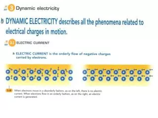
This tutorial covers designing and simulating battery power systems for electronic devices, including finding optimal battery size, efficiency, and lifetime. Learn about power subsystem components, battery characteristics, and DC-to-DC converters.

E N D
A Tutorial on Battery Simulation - MatchingPower Source to Electronic System Manish Kulkarni and Vishwani D. Agrawal Auburn University Auburn, AL 36849, USA mmk0002@auburn.edu, vagrawal@eng.auburn.edu Kulkarni & Agrawal
Contents • Introduction • Powering an electronic system • Statement of the battery problem • Power subsystem, components, characteristics • A Design Example • Circuit simulation for critical path delay and battery current • Battery simulation for lifetime and efficiency • Finding the smallest battery for required system performance • Finding battery for lifetime requirement • Finding minimum energy mode • Summary Kulkarni & Agrawal
Introduction: Powering a System IL RB VB + _ RL VL AHr (capacity) Power supplied to load, PL = IL2 RL = (VB2/RB)(RL/RB) / (1+ RL/RB)2 Ideal lifetime = AHr/IL = AHr.RB (1 + RL/RB) / VB Efficiency = PL / Battery Power = (1+ RB/RL) –1 Kulkarni & Agrawal
Lifetime, Power and Efficiency 1.0 0.8 0.6 0.4 0.2 0.0 10 8 6 4 2 0 Efficiency Lifetime (x AHr.RB /VB) Efficiency or Power PL x VB2/(4RB) Lifetime 0 1 2 3 4 5 6 7 8 RL/RB Kulkarni & Agrawal
Problem Statement Battery problem Solution Determine minimum battery size for efficiency ≥ 85% Increase battery size over the minimum size to meet lifetime requirement. Determine a lower performance mode with maximum lifetime. • Battery should be capable of supplying power (current) for required system performance. • Battery should meet the lifetime (time between replacement or recharge) requirement. • How to extend the lifetime of selected battery. Kulkarni & Agrawal
Power Subsystem of an Electronic System Kulkarni & Agrawal
Some Characteristics • Lithium-ion battery • Open circuit voltage: 4.2V, unit cell 400mAHr, for efficiency ≥ 85%, current ≤ 1.2A • Discharged battery voltage ≤ 3.0V • DC-to-DC converter • Supplies VDD to circuit, VDD ≤ 1V for nanometer technologies. • VDD control for energy management. • Decoupling capacitor(s) provide smoothing of time varying current of the circuit. Kulkarni & Agrawal
DC-to-DC Buck (Step-Down) Converter • Components: switch, diode, inductor, capacitor. • Switch control: pulse width modulated (PWM) signal. • Vout= D · Vin, D is duty cycle of PWM control signal. • References: • M. Pedram and Q. Wu, “Design Considerations for Battery-Powered Electronics,” Proc. 36th Design Automation Conference, June 1999, pp. 861–866. • L. Benini, G. Castelli, A. Macii, E. Macii, M. Poncino, and R. Scarsi, “A Discrete-Time Battery Model for High-Level Power Estimation,” Proc. Conference on Design, Automation and Test in Europe, Mar. 2000, pp. 35–41. • Power Supply Circuits, Application Note 2031, Maxim Integrated Products, Oct. 19, 2000, http://pdfserv.maxim-ic.com/en/an/AN2031.pdf Kulkarni & Agrawal
A DC-to-DC Buck Converter Vout Vin PWM control; duty cycle determines Vout Kulkarni & Agrawal
A Design Example • 70 million gate circuit. • Critical path: 32bit ripple-carry adder (RCA) • 352 NAND gates (2 or 3 inputs), 1,472 transistors. • 45nm bulk CMOS technology. • Three-step design procedure: • Circuit characterization – current and delay vs. VDD; find average current for peak performance. • Battery lifetime simulation – minimum battery size for efficiency ≥ 85% at peak performance; battery size for lifetime requirement. • Minimum energy mode – maximum lifetime VDD and clock frequency. Kulkarni & Agrawal
Critical Path Simulation • Simulation model: 45nm bulk CMOS, predictive technology model (PTM), http://ptm.asu.edu/ • Simulator: Synopsys HSPICE, www.synopsys.com/Tools/Verification/AMSVerification/CircuitSimulation/HSPICE/Documents/hspice ds.pdf Kulkarni & Agrawal
Hspice Simulation of 32-Bit RCA, VDD = 0.9V 100 random vectors including critical path vectors Average total current, Icircuit = 74.32μA, Leakage current = 1.108μA Critical path vectors 2ns Kulkarni & Agrawal
Hspice Simulation of 32-Bit RCA, VDD = 0.3V 100 random vectors including critical path vectors Average total current, Icircuit = 0.2563μA, Leakage current = 0.092μA Critical path vectors 200ns Kulkarni & Agrawal
Finding Battery Current, IBatt • Assume 32-bit ripple carry adder (RCA) with about 350 gates represents circuit activity for the entire system. • Total current for 70 million gate circuit, Icircuit = (average current for RCA) x 200,000 • DC-to-DC converter translates VDD to 4.2V battery voltage; assuming 100% conversion efficiency, IBatt = Icircuit x VDD/4.2 • Example: Hspice simulation of RCA: 100 random vectors, VDD = 0.9V, vector period = 2ns, average current = 74.32μA, Ibatt = 3.18A Kulkarni & Agrawal
Delay and Current vs. VDD 3.18A ~ 2ns (500MHz) Kulkarni & Agrawal
Battery Simulation Model Lithium-ion battery, unit cell capacity: N = 1 (400mAHr) Battery sizes, N = 2 (800mAHr), N = 3 (1.2AHr), etc. M. Chen and G. A. Rincón-Mora, “Accurate Electrical Battery Model Capable of Predicting Runtime and I-V Performance,” IEEE Transactions on Energy Conversion, vol. 21, no. 2, pp. 504–511, June 2006. Kulkarni & Agrawal
Lifetime from Battery Simulation 1008s Kulkarni & Agrawal
Finding Battery Efficiency • Consider: • 1.2AHr battery • IBatt = 3.6A • Ideal efficiency = 1.2AHr/3.6A = 1/3 hour (1200s) • Actual lifetime from simulation = 1008s • Efficiency = (Actual lifetime)/(Ideal lifetime) = 1008/1200 = 0.84 or 84% Kulkarni & Agrawal
Battery Efficiency vs. Size Kulkarni & Agrawal
Minimum Battery Size • Consider a performance requirement of 500MHz clock, critical path delay ≤ 2ns. • Circuit simulation gives, VDD = 0.9V and IBatt = 3.18A. • From battery efficiency simulation, for efficiency ≥ 85%, battery capacity should not be less than 1.2AHr, i.e., three-cell (N=3) Li-ion battery. Kulkarni & Agrawal
Battery Lifetime Requirement • Suppose battery lifetime for the system is to be at least one hour. • For smallest battery, size N = 3 (1.2AHr), IBatt = 3.18A, efficiency ≈ 93%, Lifetime = 0.93 x 1.2/3.18 = 0.35 hour • For 1 hour lifetime, battery size N = 3/0.35 = 8.57 ≈ 9. • We should use a 9 cell (3.6AHr) battery. Kulkarni & Agrawal
Minimum Energy Operation • A meaningful measure of the work done by the battery is its lifetime in terms of clock cycles. • For each VDD in the range of valid operation, i.e., VDD = 0.1V to 0.9V, we calculate lifetime using circuit delay and battery efficiency obtained from Hspice simulation. • Minimum energy operation maximizes the lifetime in clock cycles. Kulkarni & Agrawal
Minimum Energy Operation 16 14 12 10 8 6 4 2 0 Battery capacity 3.6AHr Battery capacity 1.2AHr Lifetime (x1012 cycles) 0 0.1 0.2 0.3 0.4 0.5 0.6 0.7 0.8 0.9 1.0 VDD (volts) Kulkarni & Agrawal
Summary seven-times • Battery size should match the current need and satisfy • the lifetime requirement of the system: • (a) Undersize battery has poor efficiency. • (b) Oversize battery is bulky and expensive. • 2 Minimum energy mode can significantly increase battery lifetime. Kulkarni & Agrawal