Download
1 / 40
410 likes | 457 Views
Explore additional considerations for fuel oil handling systems design, covering oil heating, insulation, safety features, and more. Learn about tank heating, overfill prevention, spill containment, day tank flow control, and air entrainment. Discover best practices for efficient and safe fuel system design.

E N D
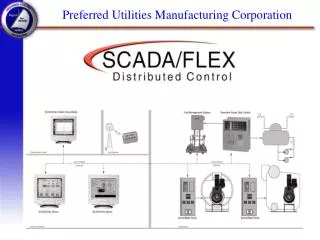
Preferred Utilities Manufacturing Corp. Fuel Oil Handling Systems Fuel System Design Considerations Part 2 31-35 South Street • Danbury • CT www.preferred-mfg.com
Additional Design Considerations • Oil Heating and Insulation • Preventing Overflows • Day Tank Flow Control • Air Entrainment • Fire Safety • Relief Valves • Multi-Tank Returns • Vent Line Height • Foot Valves • Anti-Syphon Devices
Tank Heating and Insulation • Aboveground Storage Tank (AST) – installed in a cold climate – # 2 thru # 6 oil, heating requirements and insulation of tank • Emergency generators – Approximately 40 F is the cloud point of paraffin wax in # 2 fuel oil Thermopump System application • # 6 Oil Piping - heat trace the pipe and insulate or install FOS, FOR, steam and condensate return lines in a single carrier pipe with insulation • Use a Thermopump System or a winter blend of fuel oil
Tank Overfill Prevention • Tank gauging with overfill alarm station • HLS in tank to back up the tank gauge • Model 1 Ground Level Spill Containment • Type 2 In-Wall Spill Container • Remote Overfill Alarm Station • Mechanical fill line overfill prevention device ( Type 61 and 61F) • Vent line with overfill alarm switch
Sidewalk or Driveway Fuel Fill • Spill Containers • Model 1 In Ground Spill Container • Drains oil spilled from delivery disconnect into storage tank • Designed to handle driveway traffic • Removable bellows for easy fuel testing without pavement excavation.
Model 2 In-wall Fill Cabinet Model 2 • Provides 5 Gallon Containment • For indoor storage tanks with fill lines piped to building walls • Overfill alarm • Alarm silence • Display tank level
Flow Control Filling Day Tanks in Multiple Tank Applications • Install Flow Control Manifolds • One for each day tank • Three valve by-pass arrangement for manual operation and servicing, (2) Solenoid valves • Options: Fuel filter, flow switch, oil meter, indicator lights
Day Tank Location • Day tank above main storage tank • gravity return • Provide tank overfill drain to main tank • Day tank below main storage tank • return pump system is required • pump flow rate capacity must be larger than the pump set supply system • Add a PLS switch to the tank vent
Air Entrainment • Pipe the return line to the bottom of the tank to prevent aeration • Back Pressure Regulator BPRV • Return riser pipe, install BPRV at the bottom of the riser, set pressure to maintain a constant head to prevent the free fall of the fuel and entraining air • Syphon Breaker • Day tank header system applications, can use in conjunction with the BPRV
Air Entrainment • Separate the Fuel Oil Supply (FOS) and Fuel Oil Return (FOR) Piping drop tubes in the tank to prevent the recycling of air • FOS, 4-6 inches off the bottom of the tank • FOR, 18-20 inches off the bottom of the tank, add a 90 elbow to direct return fuel away from suction
Air Entrainment VENT VACUUM BREAKER (OPTIONAL) TRAP HEADER RETURN RETURN RETURN SUPPLY SUPPLY SUPPLY ENGINE #3 ENGINE #2 ENGINE #1 RELIEF IN OUT PUMP SET
Fire Safety Basics Don’t Feed the Fire Stop the flow of the fuel
Fire Safety Shut-off Valves • Lever Gate Valve • Fully mechanical • Emergency fuel line shut-off is mandated by many codes • Fusible links open at 165F • for pipe ranges 3/4" - 3" • Fusomatic Valve • Replaceable fusible element • Fusible links open at 165F, May be manually opened/closed • for pipes 3/4" or 1"
Fire Safety Shut-off Valves • Multiple Fusible Links • Fuel Shut-off and • Limit Switch Stops Pump
Relief Valves • A must with positive displacement pumps • If the oil line is blocked, something will break • Relief valves on pump set– piped into the return line with no shut off valves • Multiple tank systems with ball/gate valve arrangement, pipe relief valve into pump suction, utilize pump flow switch for safety shutdown • Place a relief valve between two solid points to relieve hydraulic pressure from thermal expansion
Multiple Main Tank Returns • On multiple main tank applications, recommend utilizing a Tank Selector Valve that will never have a positive shutoff when changing tanks • If tank selector valve not desirable, recommend automatic ball valves with end switches. Pumps shut down during a tank changeover and will not restart until proper alignment is proven. This will also prevents a tank overfill due to improper valve alignment.
Two Tank Selector Valve • Replaces confusing array of hand valves • Simple lever operation transfers both supply & return lines from one tank to the other • Designed with no “blind spots” where flow could be blocked to or from the tanks • Threaded or flanged connections available Threaded Connection
Vent Line Vertical Height • Main Storage Tanks and some Day Tanks are only rated for 5 PSI. Tanks are not pressure vessels. • On overfilled tanks that do not provide for an overflow condition, the oil will go up the vent. • The staticpressure at the bottom of the tank can exceed the pressure rating of the tank. • Remember that 2.6 ft of #2 oil = 1 PSI • 13 feet/2.6 = 5.0 PSI • PLS switch in the vent can sound an alarm or shut off a pump.
Foot Valve Installation • Install foot valves and check valves to prevent loss of prime if top of the tank is below the centerline of the pump • Utilize an extractor fitting for easy removal of foot valve for maintenance and inspection • Extractor fitting can be a potential air leak. Insure they are properly sealed. • Foot valves are sometimes required with Anti-Syphon valves. An Anti-Syphon valve does not make a good check valve. • Insure the shipping plug is removed before installation.
Maximum Height for ASV • Install Anti-Syphon Valve (ASV) if top of the tank is above the centerline of the pump • Maximum height for ASV – 20’ above centerline of pump • Above 20’ utilize a solenoid valve for an anti-syphon device
Preferred Utilities Manufacturing Corp 31-35 South Street • Danbury • CT T: (203) 743-6741 • F: (203) 798-7313 www.preferred-mfg.com