Download
1 / 30
320 likes | 780 Views
Development of Self-Centering Steel Plate Shear Walls (SC-SPSW). Jeff Berman Assistant Professor University of Washington. NEESR-SG: Steel Plate Shear Wall Research. Jeff Berman and Laura Lowes. Larry Fahnestock. Michel Bruneau. Graduate Students:

E N D
Development of Self-Centering Steel Plate Shear Walls(SC-SPSW) Jeff Berman Assistant Professor University of Washington
NEESR-SG: Steel Plate Shear Wall Research Jeff Berman and Laura Lowes Larry Fahnestock Michel Bruneau Graduate Students: UW: Patricia Clayton, David Webster UIUC: Dan Borello, Alvaro Quinonez UB: Dan Dowden K.C. Tsai Rafael Sabelli Sponsored by NSF through the George E. Brown NEESR Program Material Donations from AISC
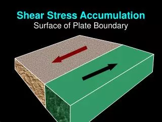
Project Overview Resilient SPSW Full-Scale Testing Analysis and Verification of Performance Subassemblage Testing Shake Table Testing Fill Critical Knowledge Gaps a ~43° Cyclic Inelastic Tension Field Action SPSW Damage States and Fragilities Coupled SPSW Testing (MUST-SIM)
Motivation • Current U.S. seismic design codes • Life Safety and Collapse Prevention • Maximum Considered Earthquake (MCE) • U.S. Earthquakes since 19701: • Only 2 people per year die due to structural collapse • $2 billion per year in economic loss Haiti Earthquake (2010) • 1 ATC-69 (2008) US Northridge Earthquake (1994)
Resilient SPSWs: Motivation • Steel Plate Shear Walls (SPSWs): • Thin web plates: tension field action • High initial stiffness • Ductile • Distributed yielding • Replaceable “fuses” (web plates) • However, • Damage in HBEs and VBEs not as easy to repair/replace How can we limit damage to HBEs and VBEs to provide a quicker return to occupancy following an earthquake? (Vian and Bruneau 2005)
Resilient SPSW: SPSW+ PT Frame VPT VSPSW D D Unloading VR-SPSW Plate yields Connection Decompression Plates Unloaded 1st Cycle 2nd Cycle D Connection Recompression Previous PT Connection Work: Garlcok et al. 2002, Christopoulos et al., 2002
SC-SPSW Research Overview Analytical Research Performance-Based Design Procedure Analysis and Verification of Performance System Behavior Experimental Research Subassembly Testing (U. of Washington) Full-scale Testing (NCREE, Taiwan) Shake Table Testing (U. at Buffalo)
R-SPSW Mechanics • Distributed loads on frame from web plates • Compression of HBE from three components: • PT • Web plate loads on VBE • Web plate loads on HBE
Performance-Based Design Collapse Prevention Repair of Plates Only V V2/50 V10/50 First occurrence of: • PT rupture • Excessive PT yielding • Excessive frame yielding • Excessive story drifts No Repair First occurrence of: • PT yielding • Frame yielding • Residual drift > 0.2% V50/50 Plate yielding Connection decompression Vwind D D50/50 D2/50 D10/50
Analytical Model • Nonlinear model in OpenSees • SPSW modeled using strip method: • Tension-only strips with pinched hysteresis • Strips oriented in direction of tension field
Analytical Model (cont.) • PT connection model: Shear transfer Rocking about HBE flanges Compression-only springs at HBE flanges Diagonal springs HBE VBE PT tendons Truss elements with initial stress (Steel02) Rigid offsets Physical Model Analytical Model • Compression-only springs at HBE flanges • Diagonal springs to transfer shear
Dynamic Analyses • 3 and 9 story prototypes based on SAC buildings: 4-6 SPSW bays • Each model subjected to 60 LA SAC ground motions representing 3 seismic hazard levels • 50% in 50 year • 10% in 50 year • 2% in 50 year • Used OpenSeesMP to run ground motions in parallel on TeraGrid machines Processor = 0 Processor = 1 R-SPSW model Processor = n-1 Ranger
Analytical Summary • Results for typical 9-story SC-SPSW • designed WITHOUT optional 50% in 50 year “No repair” performance obj. No Repair Collapse Prevention Repair of Plates Only V • Performance Objectives: • No plate repair (Story drift < 0.5%) in 50/50 • Recentering (Residual Drift < 0.2%) in 10/50 • Story drift < 2.0% in 10/50 (represents DBE) • Limited PT, HBE, and VBE yielding in 2/50 V2/50 V10/50 V50/50 Vwind D All performance objectives met !!! D50/50 D2/50 D10/50
UW Component Tests Reaction Blocks Pin to Allow VBE Rotation Roller to Allow Gap Opening Target Deformation of Specimen Laboratory Configuration Subassemblage
R-SPSW Testing Development of tension field Connection decompression Flag-shaped hysteresis Residual web plate deformation after test
Comparison of Parameters Change in number of PT strands Change in web plate thickness Kr • Affects recompression stiffness, Kr, due to change in PT stiffness • Affects decompression moment • Affects system strength and energy dissipation • Affects post-decompression stiffness
Comparison with Idealized Response • More energy dissipation than assumed • Some “compressive” resistance due to geometric stiffening VSC-SPSW Unloading Plate yields Connection Decompression Plates Unloaded D Connection Recompression 1st Cycle 2nd Cycle
Experimental testing Web Plate Behavior Study FE modeling Pins Residual Load ~25% of yield strength (Webster 2011)
Comparison with Models • OpenSees model • With and without compressive resistance in strips • Future improvements to strip model: • Modify strain hardening rules to account for cyclic yielding • Quantify compression in SPSW strip model
Frame Expansion • As PT connection decompresses, VBEs spread apart Garlock (2002) • Can cause floor damage or increase frame demands if beam growth is restrained, especially at 1st floor beam Kim and Christopoulos (2008)
Accommodation of Frame Expansion • Flexible collector beams connecting PT frame and composite slab • Applies additional point loads along beam • Damage to collector beams Garlock (2007) • Sliding interface between slab and beams • Eliminates slab restraint Kim and Christopoulos (2008)
Elimination of Frame Expansion • Rocking about HBE centerline (Pin) • NewZ-BREAKSS • Rocking about top flange only
Testing at NEES@Buffalo • Quasi-Static tests • 1/3 scale, 3-story • Various PT connection details • Full plate and Strips
Comparison of Behavior • Flange rocking provides better re-centering because of decompression moment • NewZ-BREAKSS prevents floor damage due to frame expansion.
UB Shake Table Tests • 6 degree-of-freedom shake table • Same specimens as quasi-static tests • Scheduled for completion in fall 2012
System-level Testing • National Center for Earthquake Engineering (NCREE) in Taiwan • 2-story, full scale SC-SPSW • Single actuator • Quasi-static loading • Summer 2012
NCREE Specimens • PT column base • Column can rock about its flanges
NCREE Specimens • PT column base • Column can rock about its flanges • 2 specimens • Flange rocking HBEs • NewZ-BREAKSS Connection (Top flange rocking HBEs)
Conclusions • Performance-based design procedure developed for SC-SPSW: • Elastic behavior during frequent events • Web plate yielding and recentering during DBE events • Collapse prevention during MCE events • Analytical studies show SC-SPSWs are capable of meeting proposed performance objectives • Experimental subassembly tests show ‘simple’ models are conservative and have room for improvement • Future testing will verify performance on system level
Thank You Questions?