Download

1 / 26
420 likes | 1.94k Views
12-Lead ECG Interpretation. Lead “Views”. Lead “Views”. Precordial Leads. The 12-Lead view. Each limb lead I, II, III, AVR, AVL, AVF records from a different angle All six limb leads intersect and visualize a frontal plane

E N D
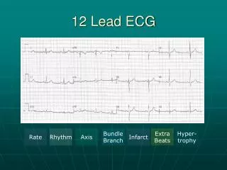
12-Lead ECG Interpretation
The 12-Lead view • Each limb lead I, II, III, AVR, AVL, AVF records from a different angle • All six limb leads intersect and visualize a frontal plane • The six chest leads (precordial) V1, V2, V3, V4, V5, V6 view the body in the horizontal plane to the AV node • The 12 lead ECG forms a camera view from 12 angles
Unipolar and Bipolar • Limb leads I, II, III are bipolar and have a negative and positive pole • Electrical potential differences are measured between the poles • AVR, AVL and AVF are unipolar • No negative lead • The heart is the negative pole • Electrical potential difference is measured betweeen the lead and the heart • Chest leads are unipolar • The heart also is the negative pole
Lead Groups I aVR V1 V4 II aVL V2 V5 III aVF V3 V6 Limb Leads Chest Leads
Inferior Wall • II, III, aVF • Left Leg I II III aVR aVL aVF V1 V2 V3 V4 V5 V6
Inferior Wall I II III aVR aVL aVF V1 V2 V3 V4 V5 V6 Inferior Wall
Lateral Wall • I and aVL • Left Arm I II III aVR aVL aVF V1 V2 V3 V4 V5 V6
Lateral Wall • V5 and V6 • Left lateral chest I II III aVR aVL aVF V1 V2 V3 V4 V5 V6
Lateral • I, aVL, V5, V6 Lateral Wall I II III aVR aVL aVF V1 V2 V3 V4 V5 V6
Anterior Wall • V3, V4 • Left anterior chest I II III aVR aVL aVF V1 V2 V3 V4 V5 V6
Anterior Wall • V3, V4 I II III aVR aVL aVF V1 V2 V3 V4 V5 V6
Septal Wall • V1, V2 • Along sternal borders I II III aVR aVL aVF V1 V2 V3 V4 V5 V6
Septal • V1,V2 I II III aVR aVL aVF V1 V2 V3 V4 V5 V6
How to record a 12 lead ECG • Clean areas of electrode placement with alcohol wipes. • Place pads for limb and chest electrodes. • Limb leads are colour coded. Pneumonic Ride Your Green Bike will help you remember how to place the leads. Start with the red lead and attach it to the right wrist. Yellow is attached to the left wrist, green to the left leg and black to the right leg.
• Position of chest leads • V1: Fourth intercostal space at the right sternal border. (First palpable intercostals space, below the clavicle is the 2nd intercostal space. • V2: Fourth intercostal space at the left sternal border • V3: Midway between V2 and V4
V4: Fifth intercostal space in the midclavicular line • V5: Anterior axillary line at the same horizontal level as V4 • V6: Mid-axillary line at the same horizontal plane as V4 and V5
The ECG Complex • The J point is the point where the S wave ends and the ST segment begins • ST elevation is measured after the J point • The ST segment is compared to the base line • The base line or isoelectric line is found at the bottom of the calibration bar J point
ST Segment • Starts with the J point • Ends with the beginning of the T wave • Elevation or depression of the ST segment is measured 0.08 seconds (2 small squares) to the right of the J point ST segment
PR Interval PR Interval • Begins at the end of the P wave • Ends at the beginning of the QRS • When determining the isoelectric or baseline find the PR interval of 2 consecutive complexes, draw a line using a straight edge and measure ST elevation from this line; this is the most accurate way to determine if the ST segment is elevated Isoelectric line
TP Segment • Begins at the end of the T wave • Ends at the beginning of the P wave • Can be used as a back up to the PR interval to determine the baseline when assessing ST elevation • Not as accurate as the PR interval TP segment
The ECG Tracing: Waves • P- wave • Marks the beginning of the cardiac cycle and measures the electrical impulse that causes atrial depolarization and mechanical contraction • QRS- Complex • Measures the impulse that causes ventricular depolarization • Q-wave- may or may not be evident on the ECG • R-wave- first upward deflection following P wave • S-wave- the first downward deflection following the R-wave • T- wave • Marks ventricular repolarization that ends the cardiac cycle
Intervals and Segments • P-R interval- • Time interval for impulse to go from the SA to the AV node • normal 0.12-0.20 secs • QRS Interval • Time interval for impulse to go from AV node to stimulate Purkinjie fibers • Less than 0.12 secs • QT Interval • Time interval from beginning of depolarization to the end of repolarization • Should not exceed ½ the length of the R-R • ST segment • end of the S to the beginning of the T