Download
1 / 47
480 likes | 674 Views
Introduction. In Electronic communication system it is impractical or impossible to interconnect two pieces of equipment with a physical facility such as a metallic wire or cable.This is true when the equipment is separated by large spans of water, rugged mountains, or harsh dessert terrain o

E N D
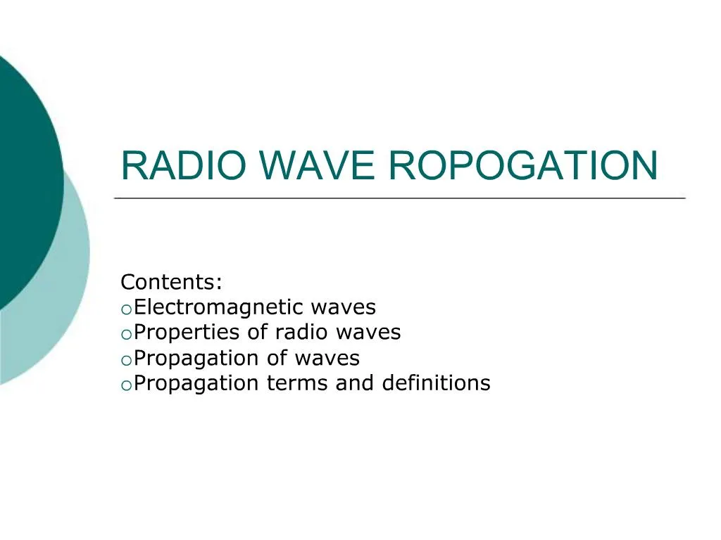
1. RADIO WAVE ROPOGATION Contents:
Electromagnetic waves
Properties of radio waves
Propagation of waves
Propagation terms and definitions
2. Introduction In Electronic communication system it is impractical or impossible to interconnect two pieces of equipment with a physical facility such as a metallic wire or cable.
This is true when the equipment is separated by large spans of water, rugged mountains, or harsh dessert terrain or when communicating with satellite transponders orbiting 22,300 miles above Earth.
3. Introduction Also when the transmitters and receivers are mobile, as with two way radio communications and cellular telephone , providing connections with metallic facilities is impossible.
Therefore Earth�s atmosphere is often used as a transmission medium.
4. Free space propagation Free Space propagation of electromagnetic waves is often called RADIO Frequency (RF) propagation or simply RADIO Propagation.
The earth�s atmosphere introduces losses and impairments to the signal that are not encountered in a vacuum.
5. TEM waves Transverse electromagnetic waves will propagate through any dielectric material including air.
However do not propagate well through lossy conductors such as sea water, because the electric fields cause currents to flow in the material that rapidly dissipate the wave energy.
6. Radio waves Radio waves are electromagnetic waves and like light propagate through free space in a straight line with a velocity of approximately 300,000,000 meters per second.
Other forms of electromagnetic waves: Infrared , Ultraviolet , X Rays, Gamma Rays.
To propagate radio waves through Earth�s atmosphere , it is necessary that the energy be radiated from the source, then the energy must be captured at the receive end.
Receiving and capturing energy are done with antenna.
7. ELECTROMAGNETIC WAVES AND POLARIZATION An electromagnetic wave is electrical energy that has escaped into free space.
EM waves travel in a straight line at approximately the speed of light and are made up of magnetic and electric fields that are at right angles to each other and at right angles to the direction of propagation.
8. Essential properties of Radio Waves Frequency
Intensity
Direction of travel
Plane of Polarization
9. Radio Waves Radio waves are a form of electromagnetic radiation similar to light and heat.
They differ from these other radiations in the manner in which they are generated and detected and in their frequency range.
10. Radio Waves It consists of traveling electric and magnetic fields, with the energy evenly divided between the two types of fields.
11. POLARIZATION The polarization of a plane electromagnetic wave is simply the orientation of the electric field vector in respect to the surface of the Earth( i.e. looking at the horizon).
If the polarization remains constant, it is described as LINEAR POLARIZATION.
12. TYPES OF LINEAR POLARIZATION HORIZONTAL: IF the electric field is propagating parallel to the Earth�s surface , the wave is said to be horizontally polarized.
VERTICAL: If the electric field is propagating perpendicular to the Earth�s surface , the wave is said to be vertically polarized.
13. CIRCULAR POLARIZATION If the polarization vector rotates 360� as the wave moves one wavelength through space and the field strength is equal at all angles of polarization , the wave is described as having CIRCULAR POLARIZATION.
14. ELLIPLTICAL POLARIZATION When the field strength varies with changes in polarization this is described as ELLIPTICAL polarization.
A rotating wave can turn in either direction. IF the vector rotates in a clockwise direction, it is right handed, and if the vector rotates in a counterclockwise direction, it is considered left handed.
15. Rays and Wave fronts Electromagnetic waves are invisible, hence they are analyzed by indirect methods using schematic diagrams.
16. Rays A ray is a line drawn along the direction of propagation of an electromagnetic wave. Rays are used to show the relative direction of electromagnetic wave propagation; however it does not necessarily represent the propagation of a single electromagnetic wave.


![G3 - RADIO WAVE PROPAGATION [3 Exam Questions - 3 Groups]](https://cdn0.slideserve.com/484375/g3-radio-wave-propagation-3-exam-questions-3-groups-dt.jpg)


![G3 - RADIO WAVE PROPAGATION [3 Exam Questions - 3 Groups]](https://cdn1.slideserve.com/3333950/g3-radio-wave-propagation-3-exam-questions-3-groups-dt.jpg)

![G3 - RADIO WAVE PROPAGATION [3 Exam Questions -- 3 Groups]](https://cdn3.slideserve.com/5901389/g3-radio-wave-propagation-3-exam-questions-3-groups-dt.jpg)