Download
1 / 42
570 likes | 1.25k Views
Direct Digital Radiography or Direct Capture Radiography. Yu zixi Radiological department Taishan Medical College. Late 1990’s. A new approach to imaging appeared DR or DDR or Direct Capture imaging Too early to tell which system will prevail. Directed Digital Radiography (DDR).

E N D
Direct Digital Radiographyor Direct Capture Radiography Yu zixi Radiological department Taishan Medical College
Late 1990’s • A new approach to imaging appeared • DR or DDR or Direct Capture imaging • Too early to tell which system will prevail
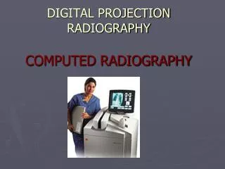
Directed Digital Radiography (DDR) Directed digital radiography, a term used to describe total electronic imaging capturing. Eliminates the need for an image plate altogether.
IMAGE CAPTURE CR • PSP – photostimulable phosphor plate • REPLACES FILM IN THE CASSETTE DR – NO CASSETTE – PHOTONS • CAPTURED DIRECTLY • ONTO A TRANSISTOR • SENT DIRECTLY TO A MONITOR
DIRECT RADIOGRAPHY • uses a transistor receiver (like bucky) • that captures and converts x-ray energy directly into digital signal • seen immediately on monitor • then sent to PACS/ printer/ other workstations FOR VIEWING
CR imaging plate processed in a Digital Reader Signal sent to computer Viewed on a monitor DR transistor receiver (like bucky) directly into digital signal seen immediately on monitor CR vs DR
Digital Radiography DDR CR Direct Capture Indirect Capture Computed Radiography (CR) - PSL Direct-to-Digital Radiography (DDR)-Selenium Direct-to-Digital Radiography Silicon Scint. Laser Scanning Digitizers
Two types of DDR systems • Both are based on the thin-film transistor as an active matrix array (AMA) • Built the size of a conventional S/F receptor
Active Matrix Array (AMA)Pixels are read sequentially, one at a time • Each TFT and detector represents a pixel • DEL = charge collecting detector element
DEL Digital Value • Digital Value depends on: • Charge collected by DEL. • Bit depth • 10 bit =1 - 1024 • 12 bit =1 - 4096
Unlike CR plates, only the exposed pixels contribute to the image data base. • One exposure = Detector Readout
DDR using cesium iodide scintillation phosphors • CsI is coated over an active matrix array (AMA) of amorphus silicon (a-Si) photodiodes • Amorphus means without shape • Photodiodes are used to detect light or measure its intensity also called a charge coupled device (CCD)
DDR steps using cesium iodide • Exit x-rays interact with CsI scintillation phosphor to produce light • The light interact with the a-Si to produce a signal • The TFT stores the signal until readout, one pixel at a time
CsI phosphor light detected by the AMA of silicon photodiodes
DDR only using amorphous selenium (a-Se) • The exit x-ray photon interact with the a-Si (detector element/DEL). Photon energy is trapped on detector (signal) • The TFT stores the signal until readout, one pixel at a time
Advantages/Disadvantages • CsI phosphors have high detective quantum efficiency (DQE) = lower patient dose • DQE = % of x-rays absorbed by the phosphors • a-Se only: there is no spreading of light in the phosphor = better spatial resolution
CR & DR 4000 x 4000 image only as good a monitor* 525 vs 1000 line more pixels = more memory needed to store resolution dependent on pixel size CR 2-5 lp/mm RAD 3-6 lp/mm DR 3-5 lp/mm IMAGE APPEARS SHARPER BECAUSE CONTRAST CAN BE ADJUSTED BY THE COMPUTER – (DIFFERENCES IN DENSITY) Image Resolution –(how sharply is the image seen)
Pixel Pitch • Spatial resolution determined by pixel pitch. • Detector element (DEL) size • 140 μm = ~3.7 lp/mm • 100 μm = ~ 5.0 lp/mm
Signal Sampling Frequency Good sampling under sampling
DR • Initial expense ---high • very low dose to patient • image quality of 100s using a 400s technique • Therfore,¼ the dose needed to make the image
Flat Panel TFT Detectors • Have to be very careful with terminology • One vendor claims:“Detector has sharpness of 100 speed screen” • May be true: TFT detectors can have very sharp edges due to DEL alignment • But , Spatial resolution is not as good as 100 speed screen. • TFT detector = 3.4 lp/mm • 100 speed screen = 8 – 10 lp/mm
TFT Array Detectors • Detector is refreshed after exposure • If no exposures are produced. . . detector refreshed every 30 – 45 sec • Built in AEC, An ion chamber between grid and detector
Patient Dose • Important factors that affect patient dose • DQE: when using CsI systems • Both systems “fill factor” • The percentage of the pixel face that contains the x-ray detector. • Fill factor is approximately 80%
DDR has all the advantages of CR imaging techniques • Post processing & PACS
Advantages of DDR • Fast speed, large throughput • High spatial resolution • Low patient radiation dose • Can be updated • Less noise • Powerful post-processing