Download
1 / 40
410 likes | 470 Views
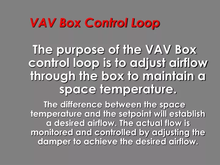
VAV Box Control Loop. The purpose of the VAV Box control loop is to adjust airflow through the box to maintain a space temperature.

E N D
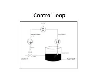
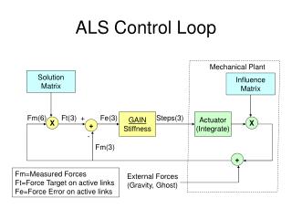
VAV Box Control Loop • The purpose of the VAV Box control loop is to adjust airflow through the box to maintain a space temperature. • The difference between the space temperature and the setpoint will establish a desired airflow. The actual flow is monitored and controlled by adjusting the damper to achieve the desired airflow.
VAV Box Control Loop Space Temperature Analysis Desired Flow Setpoint DDC Control Calculations Signal to VAV Box Damper Actuator Air flow through box into space
VAV Box Control Loop Crossflow Sensor Damper Damper Actuator Differential Pressure Transducer Metal Enclosure DDC Controller T 24 VAC Transformer TemperatureSensor BAS Communication Trunk
VAV Box Control Loop VAV Box Control Logic
VAV Box Control Loop • VAV Box Control Logic Desired Air Flow Rate Between Flowmin and Flowmax Zone Temp. Output Control Span Routine Temperature Control Loop Flow Control Loop Offset Amount of Reset Required 0% to 100% Calculated Damper Position 0% to 100% Differential Pressure
VAV Box Control Loop • Temperature Control Loop • The temperature control loop setpoint is calculated by taking either the occupied or unoccupied setpoint and adding the offset from the slider on the thermostat. • Offset is typically ±2°C.
VAV Box Control Loop • Temperature Control Loop • The temperature control loop calculates an 0% to 100% output using a proportional plus integral algorithm. The output is based on the difference between the zone temperature and setpoint, the proportional band and the integral time. If the temperature is within the deadband of the setpoint, the output is 0%. • 0% : min. cooling 100% : max cooling
VAV Box Control Loop • Temperature Control Loop Unoccupied Setpoint Occupied Setpoint Proportional Band Select Mode Integral Time Deadband (0.17°C) Remote Setpoint Offset Setpoint Output Command Temperature Control Loop + 0% - 100% Zone Temperature
VAV Box Control Loop • Temperature Control Loop • Network Visible Points Zone Temp Offset Occ SP Unocc SP Setpoint Temp. PB Temp. IT Temp. Cmd
VAV Box Control Loop • SPAN Function • The SPAN Function calculates the desired flow through the VAV box. The desired flow is between the minimum flow value and the maximum flow value based on temperature control loop output. Minimum flow value and maximum flow value will depend on mode of box. Output of SPAN Function (Flow SP) can be overridden for testing.
VAV Box Control Loop • SPAN Function Unoccupied Minimum Unoccupied Minimum Occupied Minimum Occupied Minimum Select Mode Select Mode Minimum Maximum From Temperature Control Loop Desired Flow To Flow Control Loop SPAN 0% = Minimum 100% = Maximum 0% to 100% Minimum to Maximum
VAV Box Control Loop • SPAN Function • Network Visible Points Occ Min. Unoc Min. Occ Max Unoc Max Temp. Cmd Flow SP
VAV Box Control Loop • Flow Control Loop • Actual Flow is calculated from velocity pressure sensor input. • Actual flow is compared with desired flow as calculated by SPAN function using a Proportional + Integral (PI) control loop. If the difference between the desired air flow and the measured air flow is less than the deadband, the output is 0%.
VAV Box Control Loop • Flow Control Loop Proportional Band Box “K” Factor Integral Time Deadband Box Area Desired Flow from SPAN Function Flow Control Loop Output Signal from P Sensor 0% - 100% Calculated Flow
VAV Box Control Loop • Flow Control Loop • Network Visible Points DiffPress Airflow Box Area Box Mult Flow SP Flow PB Flow IT Flow DB Dpr Posn
VAV Box Control Loop • Output Control • The Output Control Module receives the signal to position the damper from the Flow Control Loop and either opens or closes the damper to achieve the desired position. • The signal is not passed to the output if the shutdown open or shutdown close is active or if the damper is less than the minimum position.
VAV Box Control Loop • Output Control Damper Stroke Time Minimum Damper Position Shutdown Open Close From Flow Control Loop Damper Open Output Control 0% to 100% Damper Close
VAV Box Control Loop • Output Control • Network Visible Points Dpr Posn Dmpr Cmd Dpr Time Dpr Min. Dmpr Opn Dmpr Cls
VAV Box Control Loop Diagnostics
VAV Box Control Loop • Diagnostics • A VAV box is a small mechanical system mounted above the ceiling in an office area. • Diagnostics are required to recognize and report common system problems.
VAV Box Control Loop • Diagnostics • Starved Box • If the damper is 100% open and the desired airflow cannot be achieved, the starved box flag is set. • Common causes of starved boxes are:- Duct static pressure too low- Actuator motor burned out- Damper blade is jammed
VAV Box Control Loop • Diagnostics • Space Temperature • The difference between the actual space temperature and the space temperature setpoint is averaged over time. • This is a good first place to look to identify VAV box problems
VAV Box Control Loop • Diagnostics • Space Temperature • Large average deviations (>1°C) caused by: • unreasonable setpoint entered • box unable to provide sufficient cooling due to low duct static pressure or maximum airflow parameter too low • temperature sensor incorrectly located
VAV Box Control Loop • Diagnostics • Box Flow • The difference between the actual air flow through the box and the calculated air flow setpoint is averaged over time. • Large average deviations (>5% flowmax) caused by: • Calculated setpoint is not achievable • Wrong flow control loop parameters
VAV Box Control Loop • Diagnostics • Actuator • The duty cycle for the actuator is calculated: • Time actuator is receiving positioning signalTime controller is running • A duty cycle in excess of 5% indicates that box is cycling and the flow control loop parameters are wrong.
VAV Box Control Loop Temperature Sensor
VAV Box Control Loop • Temperature Sensor Mounted at 1.5m on inside wall, away from sunlight. Local setpoint adjustment allows occupant to modify the setpoint by ±2°C (adjustable). This has a psychological effect on occupants.
VAV Box Control Loop • Temperature Sensor Button allows occupant to request overtime or put system in boost mode. Sensor has connection point for hand held device used for balancing.
VAV Box Control Loop Air Flow Measurement
VAV Box Control Loop • Air Flow Measurement This tube has holes facing away from air flow This tube has holes facing toward air flow Direction of Air Flow H = Total Pressure L = Static Pressure H - L = Velocity Pressure CFM = 4005 x Velocity Pressure x Box Area H L K factor
VAV Box Control Loop • Air Flow Measurement • DDC Controller measures differential pressure (velocity pressure) from cross flow sensor and converts into air flow. • Auto zero algorithm automatically calibrates reading on request or at a scheduled time.
VAV Box Control Loop Damper Actuator
VAV Box Control Loop Damper Actuator Output can be positioned between 0° and 90° (±1°) by sending timed pulses to either open or close. DDC Controller keeps track of damper position. With the damper position, the DDC Controller ensures that the actuator is not overdriven.
VAV Box Control Loop • Damper Actuator Common/Open Voltage 24VAC Damper has atorque of 4 N-m. t Common/Close Voltage 24VAC Open Damper Actuator Common t Close Open for 4.5 sec (3.4 °) Close for 3 sec (2.3 °) Stroke time (0° to 90°) = 120 seconds
VAV Box Control Loop Pressure Dependent VAV Box
VAV Box Control Loop • Pressure Dependent VAV Box • A Pressure Dependent VAV Box includes: • Temperature Sensor • Damper and actuator • DDC Controller • A Pressure Dependent VAV Box does not include: • Crossflow sensor and differential pressure sensor
VAV Box Control Loop • Pressure Dependent VAV Box Damper Damper Actuator Metal Enclosure DDC Controller T 24 VAC Transformer TemperatureSensor BAS Communication Trunk
VAV Box Control Loop Pressure Dependent VAV Box Damper Stroke Time Minimum Damper Position Proportional Band Integral Time Shutdown Deadband (0.17°C) Open Close Damper Open Zone Temp. Output Control Temperature Control Loop Damper Close Offset Calculated Damper Position 0% to 100%
VAV Box Control Loop • Pressure Dependent VAV Box • A pressure dependent box is slightly less expensive than a pressure independent box but has the following disadvantages: • Less responsive to changes in load • More difficult to balance and troubleshoot • Use more energy as static pressure reset is not possible
VAV Box Control Loop • Conclusion • Integrating VAV Box DDC Controllers into the BAS has the following advantages when compared to stand-alone DDC controllers: • Save energy by using static pressure reset • With Diagnostics, the operator can know about problems before a tenant calls • Operator can display and keep record of space temperatures