Download
1 / 23
230 likes | 429 Views
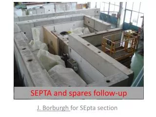
J. Borburgh. Kicker and Septa status and expected performance at the 2006 start-up. With input from:

E N D
J. Borburgh Kicker and Septa status and expected performance at the 2006 start-up With input from: B. Balhan, E. Carlier, F. Caspers, L. Ducimetière, T. Fowler, E. Gaxiola, B. Goddard, M. Hourican, Y. Kadi, T. Kroyer, T. Masson, M. Meddahi, V. Mertens K. Metzmacher, A. Prost, L. Sermeus
PS kicker issues PS septa re-installation and spare situation SPS kicker issues and spare situation SPS septa status and spare situation SPS diluter (septa protection) limitations Conclusion SPS multi-cycling reservations Outline
Ion injection KFA28 becomes operational in 2006. System impedance will be reduced from 25W to 12.5W. Control software will be integrated into the DSC also controlling KFA45 (dcpsk45.cern.ch). KFA45 & KFA71-79 vacuum tanks were vented to atmosphere owing to PS Main Magnet refurbishment. Both systems will require high-voltage reconditioning of the magnets. Modified all KFA71-79 HV transmission gas filled cable junctions Modified and recalibrated all KFA71-79 HV terminating resistors General fluid systems modifications Still a lot of work needs to be done to get everything up and running, but no problems are envisaged PS Ring Kickers
PS ComplexKickers Major renovation of the B174 HV test area allows improved testing and preparation of spares with better security: • BI.DIS spare pulsed power supply currently being recommissioned (inherited in 2003). • Test system (spare KFA71 and KFA79 magnets and tanks plus two HV pulse generators) presently being rejuvenated. • Development of new modular fluids system underway • Development of switched HV load for ISOLDE target power supply dynamic response studies • Construction of new HV cable shed provides improved protection and logistics
AD: Planned removal of kicker tank K35 (p injection via the loop). This requires changes to the DSC control RTT for AD extraction (dadekik2.cern.ch). Two HV pulse generators and one vacuum tank containing two magnets become available as spares. ISOLDE: Parallel operation of positive and negative 60kV power supplies requires controls RTT modification (disoht.cern.ch). Consequently increased voltage stress in HV changeover switch. PS ComplexKickers
Installed: SMH16.1 The braze on the coil connection which leaked in July 2004 has been repaired (has served 6 weeks in 2004). Septum Re-installation: PS SMH16 Spares: • SMH16.2 (full spare): in PS from 19.7.2004 onwards with 1 new coil and 1 coil with 6 years of service. • 2 yokes with new coils. Consolidation budget requested for additional vacuum vessel to complete the second full spare in 2006.
Installed: SEH 23.2: overhauled as new SEH 31.1: overhauled as new New 3M FC-77 insulating liquid replaces the SHELL Diala oil in feedthrough for SEH31 Conversion of SEH23 feedthrough for sd. 06/07 or sd. 08/09 depending on if and when the new MTE will be installed Re-installation of PS Electrostatic Septa Spares: • SEH 23.1: to be overhauled in spring 2006 • SEH 31.2: new, never installed before • SEH 31.3: 2 yrs of exploitation, to be overhauled • HV cable (pp300B); 160 m of old stock, and new replacement cable being ordered (consolidation prog.)
LSS6 converted from slow extraction to fast extraction during 2005 4 MKE’s installed Safety measures implemented on MKE’s in LSS4 MKP kicker rise time improvement to be completed before start-up Upgrade of the MKQ timing system for multi-cycling operation Overview of Principal SPSKicker Modifications Reminder: Sparks observed during the 2004 run on the MKDV are still under investigation.
Installed: LSS1: 4 MKP, 2 MKDV, 3 MKDH, 1 MKQH, 1 MKQV LSS4: 5 MKE LSS6: 4 MKE Operational spares: 2 spare MKP (1 type 5 modules, 1 type 2 mod., type 4 mod. to be rebuilt) 1 MKDV (but still to be pulse tested) 1 MKE SPS Kicker Spare Situation
4 MKE magnets installed System of short circuited type (instead of characteristically terminated) (ref. LTC 16.11.2005) Advantage: despite doubling the rise and fall time (but still within spec, i.e. <10 µs) , the required kicker voltage is reduced → improves the reliability. 1 of 4 magnets is partially equipped with beam impedance reduction measures, which equally reduce the beam induced ferrite heating If such beam impedance reduction measures prove successful and workable in beam operation, this could be applied to all 9 MKE’s in LSS4 and LSS6 as from 2007 or later (depending on workload) 4 new MKE’s in LSS6
MKE Beam Impedance Reduction with Stripes Printed Directly on Ferrites Interdigital comb structure 20mm spacing Ref.: E. Gaxiola et al, “Experience with Kicker Beam Coupling Reduction Techniques”, PAC’05
Safety measures implemented for extraction kicker generators in SPS ECA4 4 silicon fluid self healing capacitors replace 52 mineral-oil-filled capacitors Fire retardant wall SPS Extraction Kickers MKE LSS4
Rise time improvements for MKP #4 started in 2004 Replacement of broken damping resistors of PFN #1 - #6 Final fine tuning to be completed on PFN #7 and #8 before start-up 2006 Goal: rise time of < 220ns SPS Injection Kicker MKP
LSS6 fast extraction installed: 1 TPSG6; 2 MST; 5 MSE (5 ZS moved to storage as spares for LSS2) Septa position definition changed: position refers to protection element position (most upstream component) Septa coil and yoke temperature sensors have been disconnected on MST/MSE in LSS4 and LSS6 in order to cure electro-magnetic coupling with LHC beam type. Interlock on girder position added for LSS4 and LSS6 extraction (Connection to the Extraction Permit) Overview of Principal SPS Septa Modifications
Installed: LSS2: 5 ZS; 1 TPSN; 3 MST; 5 MSE LSS4: 1 TPSG4; 6 MSE LSS6: 1 TPSG6; 2 MST; 5 MSE Spares: 5 ZS recovered from LSS6, plus additionally 1 spare for ZS1 or ZS2 (invar anode, 60 µm wires) and 2 spares for ZS4 or ZS5 (stainless steel anode, 100 µm wires). 4 MST 5 MSE No spare for TPSN Previous type TPSG4 to be upgraded to present design during 2006, but now serving as (low intensity) spare Spare TPSG6 to be built in second half of 2006 SPS Septa Spare Situation
TPSG (Septa Protection) Elements TPSG4 (LSS4) Improved design with different absorbing materials, additional length and water cooling installed • TPSG6 (LSS6) • Newly designed, built and installed
TPSG Diluter Performance Maximum proton intensity equipment limits in case of full impact on diluter Reminder: LHC NOMINAL intensity in SPS: 3.3e13 protons total LHC ULTIMATE intensity in SPS: 4.9e13 protons total CNGS NOMINAL beam intensity: 2.4e13 protons / batch (2 batches in SPS in total) CNGS ULTIMATE beam intensity: 3.5e13 protons / batch (2 batches in SPS in total)
TPSG Diluters Performance • A beam sweep (as produced by a kicker failure) can be sustained without any damage and the diluter properly protects the downstream septa. • Both diluters will be able to properly protect the downstream MS septa from full impact but the diluters themselves are likely to be irreversibly damaged by the LHC nominal intensity beam!
Given the space constraints and due to the unavailability of the ultimately desired materials for the diluter during the construction period, more common and well specified materials are used for the time being, yielding the performance as mentioned before. Upgrading from graphite and Ti to C-C and γ-met should yield more robust diluters, although the resulting performance is still to be confirmed by calculations from CRS4. 2006 and onwards should see the validation and subsequently the construction of upgraded (spare?) TPSG’s TPSG Upgrade
TPSG4 Behaviour in Case of Full Impact of Ultimate LHC Beam Temperature rise of every diluter block Maximum Stassi ratio for a 250ms simulation
TPSG6 Behaviour in Case of Full Impact of Ultimate LHC Beam Temperature rise of every diluter block Maximum Stassi ratio for a 250ms simulation
PS kickers: Still a lot of work needs to be done to get everything up and running, but no problems are envisaged PS septa: re-installation well under way. Installation of new type of HV feedthrough on SEH31 on critical path. SPS: New fast extraction channel at LSS6 nearly installed SPS kickers: MKP rise time improvements to be completed before start-up. MKE in LSS6 of short circuited type to improve reliability. SPS diluters: properly protect septa in all cases, but may likely be damaged in case of full impact by LHC nominal type beam on the diluters Conclusions
Presently we cannot simply assume that the ZS, “as is”, in position and with nominal HV on, is ready for fast multi-cycling. More tests on the spark rate with high intensity beams are needed. A potential solution may be to ramp down (t ≈ 8 s) the HV during high intensity operation, but this is still a slow process that may not allow full & fast multi-cycling. Outstanding issues: Add interlock (BIC?) to prevent bumped beam if during CNGS or LHC operation Interlock on girder position If ramping solution will be retained, additional interlocks are needed to verify the absence/presence of Unom. ROCS may be a suitable tool to manage the current/voltage settings Interleaved mode operation with a slow extraction has to be studied for LSS2 MST/MSE extraction (i.e. temperature sensors may heat-up due to LHC beams and stop the extraction channel) The new items will need careful commissioning before well functioning can be taken for granted. Limitations on Multi Cycling (from MCSG)