Download
1 / 20
200 likes | 354 Views
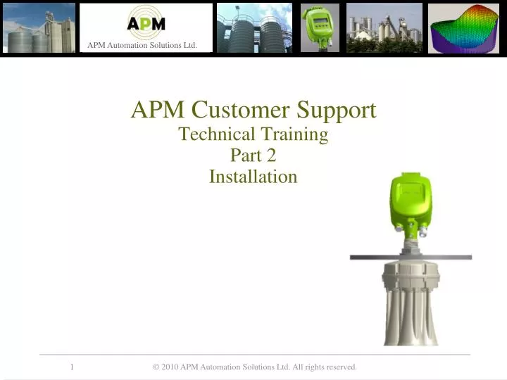
APM Customer Support Technical Training Part 2 Installation . Agenda. Selecting location / Locator Physical Installation Scanner Parts Technical specifications and Wiring Tools Mounting, Orientation and flange Neck extension / Head Separation Documentation Application Approval Form (AAF)

E N D
Agenda Selecting location / Locator Physical Installation Scanner Parts Technical specifications and Wiring Tools Mounting, Orientation and flange Neck extension / Head Separation Documentation Application Approval Form (AAF) Installation Preparation Form (IPF) Startup Guidelines Complete of Installation(COI) Case Studies
Scanner Locator Use the Scanner Locator for optimal mounting position • Provides optimal location based of vessels dimensions, filling and emptying points • Allows entering of reference points and a measuring ruler • Configuration can be saved as XML file or as a jpg
3DLevelScanner Parts – Terminology • The 3DLevelScannr is divided into two parts • Transducers case: • Three Antennas, sealed with a customized tin foil • 52mm (2.04”) thread to fasten the scanner to a flange and a fastening nut • Temperature sensor • Sealing rubber ring • Orientation indications • Scanner’s Head: • Contains the electronic board (EC) • One gland and one blind gland • Grounding screw • Fastening screw to the transducers
Measurement Characteristics • Frequency: 2.6 - 7 KHz (4.5kHz default) • Beam angle: 30° - 110° (70° default) • Accuracy (vertical): 15 mm (0.6 ”) • Measuring range: 0.5 - 70 m (1.6’-230’) • Dead zone: 50 cm (20”) from flange • Temperature Accuracy: 0.5°C (0.5°F)
Environment and Certifications • Process temperature: -40° – 85°C (-40 – 185 °F) • Process pressure: -0.2 – 3 bar • Protection: IP 67 • ATEX II 1/2D, 2G (Head-zone 21, Antenna-zone 20) • FM CL I,II Div I GP CDEFG • CE EMC EN61326 • CE Safety IEC EN61010-1 • FCC 47CFR part 15 subpart B • ISO 9001 2000
Interfaces Power supply: 20-36 VDC Nominal power supply: 24 VDC Max current consumption: 120mA, 3W Interfaces: 4-20mA (PLC - Passive) / HART RS-485 / ModBus GSM (CSD), GPRS TCP/IP Baud Rate: RS-485 – 115200 bps HART – 1200 bps RS-485 max distance: < 1000m (3280’) Max number of devices: 64 (single RS-485 bus)
Wiring the 3DLevelScanner • RS485 cable – Twisted pair, Shielded, 120Ohm impedance • RS-485 requires 120Ohm Resistors in both ends of the daisy-chain • 4-20mA – Passive PLC • 24 VDC Power Supply
Wiring the 3DLevelScanner • Single scanner with a 3DLinkPro and HART
Recommended Tools • The site application documents (IPF, AAF), and Silo drawings • Set of small precision screwdrivers (for the terminal blocks) • 13mm open wrench • 4mm Allen Key (preferably with a handle) • Large adjustable wrench 18” • Stanley knife, Cutter, Pointed pliers, Insulating tape • Laser measurement device (or other means to ensure correct positioning and distance to the material) • RS485 to USB converter, including drivers • 120Ohm and 250Ohm resistors • PC/Laptop
Positioning Guidelines Important guidelines: • Not close to the filling point and not too far • Clear vision to peak of material at maximum level • Flange to be horizontal (scanner at 90° to the ground) • At least 10 mm (0.4”) gap between the socket’s bottom (or any other obstacle) and the antenna's bottom
Positioning Guidelines (cont.) Orientation: • The mounting direction is indicated by a tendon on the transducers enclosure and a notch on the top of the thread fastening the flange • The 0º should point to the center of the vessel (including square vessels and open bins)
Mounting the 3DLevelScanner • The Transducer case must fit the hole in the silo, if not another solution can be found with neck extension or by lowering the scanner inside the silo • The widest part of the scanner is the transducers case: 193.3 mm (7.61”) • Insert the flange onto the neck tube • Screw the nut to the neck thread and tight using an 18” adjustable wrench • Note: The diameter of the hole in the flange center is 52 mm (2.1”)
Mounting the 3DLevelScanner • Flanges’ thickness is 6.5mm (0.25”)
Neck Extension • The Neck extension is available in three sizes: • 20cm = 8inches • 30cm = 12inches • 50cm = 20inches • The neck extension must be purchased with a compatible scanner, an adjusted antennas cable is manufactured with the scanner and compatible with the require neck extension
Head-Body separation • The Head-Body Separation kit is available in three size : • 1m = 3ft • 2.5m = 8ft • 10m = 33ft
Documentations - AAF • Application Approval Form (AAF) • Provides background information and important data regarding a required application • Go / No-Go – Simplify the approving procedure of new applications • Provides basic understanding of customer’s expectations from the 3DLevelScanner • Helps in deciding which product best fit the application (S / M / MV / MVL) • To better understand the application, it is recommended to request a detailed silo drawing
Documentations - IPF • Installation Preparation Form (IPF) • Provides all required data to prepare the site and to configure the scanner • To be filled after application approval Form (AAF) • Main Objective – Maximum information before shipping & installing the 3DLevelScanner • This form must be accompanied with detailed drawing of the vessel
Documentations – Startup Guidelines • Startup Guidelines (SG) • Provides an overview of all required subjects that need to be observed by the installer • To be filled with all important additional information that is not covered by the IPF