Download
1 / 25
260 likes | 511 Views
HIGH PRECISION PERFORMANCE OF LHC POWER CONVERTERS. POCPA Conference 14..16 June @ CERN. Miguel Cerqueira Bastos (TE-EPC-HPM). CONTENTS. The LHC Power Converters High Precision components Testing and Calibration infrastructure High Precision strategy

E N D
HIGH PRECISION PERFORMANCE OF LHC POWER CONVERTERS • POCPA Conference • 14..16 June @ CERN • Miguel Cerqueira Bastos (TE-EPC-HPM)
CONTENTS • The LHC Power Converters • High Precision components • Testing and Calibration infrastructure • High Precision strategy • Results from tunnel tests and calibrations • Remote control and current reference generation • The current loop • Results from tracking tests • Conclusions
lhc power converters • LHC powering challenge • 8 independent powering sectors, each with one • main dipole circuit and two main quadrupole circuits • A multitude of circuits with different powering and • accuracy requirements ! • The “high-precision” challenge: • Generate and synchronise 24 different current reference functions for the main power converters –> main dipoles and quadrupoles -> power converter: Inom=13kA • Control the currents in all the main circuits within a few parts per million (ppm) of nominal current (1ppm = 13mA): • High accuracy current • measurement • No tracking error • No overshoot Pt 7 Pt 8 LHCb Pt 6 Pt 1 ATLAS Pt 2 Pt 5 CMS ALICE Pt 3 Pt 4
lhc power converters • LHC powering -> a multitude of circuits with different powering and accuracy requirements ! • Where to start ? • Converters grouped in few categories • Accuracy classes defined at early design stage
Lhc power converters • LHC ±120A,±10V300 Units • ACCURACY CLASS 4 • Inner Triplet (IT) correctors, dipole orbit correctors • CERN Design • Switch-mode converter • LHC ± 600A,± 10V400 Units • ACCURACY CLASS 3 • Multipole correctors • External Design • Switch-mode converter • LHC 4..6kA,08V200 Units • ACCURACY CLASS 2 • Separation dipoles, insertion quadrupoles • External Design • Switch-mode converter • LHC 60A,08V752 Units • ACCURACY CLASS 4 • Dipole orbit correctors • CERN Design • Switch-mode converter
Lhc power converters • LHC13kA,±190V8 Units • ACCURACY CLASS 1 • Main dipoles • External Design • Thyristor converter • Calibration/Precision Rack • 16 locations • ACCURACY CLASS 1 • Used with: • LHC 13kA 18V • LHC13kA ±190V • Inner Triplet converters • LHC 13kA,18V16 Units • ACCURACY CLASS 1 • Main quadrupoles • External Design • Switch-mode converter
LHC POWER CONVERTERs • High performance requires a subsystem approach • LHC power converters are composed of 3 main subsystems: • Voltage Source (power part) • Digital control electronics (FGC) -> high performance current loop • Current transducers (DCCTs) -> high performance current loop Iout ACMainsSupply • Voltage Source • (power part) • « Voltage amplifier » • Magnet Protection Magnet Vout CoolingSystem MagnetProtection A B digital.... analog Vref • Digital Controller (FGC) • Volt. Source Control • High Prec. Digital loop • Com. with LHC Control CurrentTransducers (DCCTs)head & electronics IA ControlWorldFip- I ref - Earth Circuit IB AC Mains Supply AC Mains Supply Magnet Protection Detection system & General Interlock Controller
Digital control electronics - FGC • FGC [Function Generator Controller] • Reference function generation, digital current regulation, measurement acquisition • Only 2 types for all LHC converters ! • The difference is the internal ADC board: • FGC-COD ->SAR ADC for lower precision • [only used for LHC60A-08V > accuracy class 4] • FGC-Generic -> Delta-Sigma ADC for medium to • high precision [accuracy class 2, 3 and 4 converters] The FGC- Function Generator controller • For the very high precision (accuracy class 1): main dipoles, main quadrupoles and inner triplet converters, a generic FGC is used but a dedicated external ADC is used instead of the internal one: • 22-bits DELTA-SIGMA ADC • CERN Design • Output signal transmitted by fibre-optics to the FGC • Installed in an separate EMC, temperature controlled rack The CERN 22 bit Delta Sigma ADC
Current transducers –dccts • Class 1-2 High Precision: 4-13kA DCCT • Separate head (magnetic part) and electronics • Five ratings of nominal currents (4kA, 5kA, 6kA, 7kA, 13kA) • Head equipped with a calibration winding for calibration: calibration by injection of a reference current in the cal winding ! 4..13kA DCCT Magnetic Head • Class 3 - Medium Precision: 600A DCCT • Separate head (magnetic part) and electronics • Electronics located in the FGC chassis • Local calibration using a special calibration chassis • Class 4 - Low Precision: 120A DCCT • Integrated Head and Electronics • Initial calibration done locally using a reference DCCT 4..13kA DCCT Electronics 600A DCCT head 120A HitecDCCT 120A Ritz DCCT 600A DCCT Electronics
Testing and calibration infrastructure • A complete calibration infrastructure was built to cope with the LHC requirements for high precision current measurement: • The CERN standards laboratory which keeps a set of eleven 10V reference standards and resistance standards (1Ω..10k Ω), traceable to national standards • A unique 10mA transportable reference standard especially develloped for CERN (called PBC), traceable to national standards via 1kOhm and 10V standards. This device is at the basis of CERN’s current calibration infrastructure. 10mA-> 10V, 1kΩ traceability A set of CERN’s transportable 10mA, 10V current standards, traceable to international standards
Testing and calibration infrastructure • High accuracy DCCT measurement test-beds (600A, 6kA, 20kA) equipped with reference DCCTs -> a group of selected and specially improved high-current DCCTs used as reference devices) • The CDC (CERN DCCT Calibrator): a 0 to ±5A programmable reference current source with ppm accuracy, designed at CERN. The CDC is used for calibration of DCCTs with calibration windings. The 6kA DCCT testbed DCCTs under test DCCT calibration and traceability The CERN Current Calibrator
Testing and calibration infrastructure • For accuracy class 1a fixed calibration system using the CDC has beeen foreseen in the tunnel for remote calibration of the power converters. • For the other converters, mobile calibration units have been foreseen, for easy calibration of the power converters in the tunnel A Mobile calibrator used to calibrate a 6kA converter Accuracy 1 fixed calibration system installed in special EMC, temperature controlled racks
calibration infrastructure – FGC and database • In the FGC, a number of properties implement a model of the ADC and DCCT errors. • Calibrations are done by memorising calibration constants in the FGC. In operation, the FGC continuously recalculates the output value of the device being corrected. • An image of the FGC configuration properties is stored in a central database and a synchronisation scheme ensures that the properties in the database remain a faithful image of the FGC properties at all times. • Some of these properties are modified during calibrations (DCCT, ADC errors). Others are used as read-only properties (TC, temperature, etc).
High precision strategy • The power converter output current accuracy is largely determined by DCCT and ADC employed. • These components were thoroughly tested before installation and need to be maintained over the life of the accelerator. Six interventions can be discerned: • Testing of subsystem by manufacturer • Reception tests at CERN • Converter Integration tests • Commissioning tests • Calibration after repair or exchange of the subsystem • Periodic calibration to guarantee long-term accuracy • High Precision DCCTs: calibration performed by injection of a reference current in the calibration windings. • ADCs: calibration performed by applying a reference voltage to the input of the ADCs. For the FGC internal ADCs this is done automatically each 24h when the converter is OFF. The reference voltages are verified every year using DVMs which themselves are calibrated using 10V reference standards -> traceability.
Reception tests • All DCCTs, were tested in special testbeds on arrival at CERN. 4000 DCCTs were tested in total. • 2000 FGCs were tested and burnt in in a special facility receiving 200 FGCs at a time • 100 CERN 22bit ADCs individually tested on a dedicated testbed. Internal ADCs were tested in a separate setup.
Integration and tunnel tests • Once all subsystems were integrated into the power converters, the overall high precision performance was tested in specially-built test-beds, equipped with reference DCCTs • After installation in the tunnel, performance type tests were performed in all types of converters using the current calibrator or a reference DCCT Integration tests results in ppm peak-to-peak for short term stability, LF noise, reproducibility main dipole power supply 30min stability at 2kA -> within 0.3 ppm !! main quadropole power supply 30min stability at 6.5kA -> within 0.3 ppm !!
Remote control and reference generation • Control of the LHC requires that all of the power converters be controlled together and their operation synchronised • In order to achieve synchronised control of the converters, the FGCs are connected by groups of 30 units to 73 x WorldFIP real-time fieldbus segments • Each one of this WFIP segments is connected to the LHC controls ethernet by a gateway front-end computer • The power converters are controlled using client applications that send commands to the gateways which then relay the commands to the FGCs over the WorldFIP.
Remote control and reference generation How is the reference generation in all FGCs synchronised? • Each gateway has a timing receiver connected to the LHC timing network, providing GPS-synchronised UTC time and LHC timing event data • The timing signal is used to generate a 50Hz trigger signal to synchronise the cycles of all WorldFIP buses • Each FGC uses the start of each WorldFIP cycle in a phase-locked loop to synchronise its local clock to within 1E-7, with jitter of less than 1E-6 s • Synchronisation of the starting and aborting of references is achieved using timing events sent over the LHC timing network. Gateway PCs installed in an LHC access point
The current loop • To achieve the high precision requested for the control of the currents in the LHC, an RST digital current loop is implemented within each power converter’s FGC • This type of current loop has the advantage of decoupling the problem of the tracking of the reference from the problem of regulation (rejection of perturbations). • This control strategy allows the current reference to be followed with high precision without tracking erroror overshoot and minimizes voltage noise at the power converter output Current regulation loop in main LHC power converters
The current loop • The role of the current loop is to follow the current reference sent by the LHC control room with high precision and to compensate for the imperfections in the circuit model. • The bandwidth of the current loop can be relatively low (0.4..1 Hz) and current loop sampling period large (0.1 s). The RST loop is well adapted to the LHC as inductances and time constants are high (16.6H and 20’000s for MD and 0.25H and 250s for MQ). Regulation error in 1.1TeV ramp for main dipole and quadrupole power converters of sectors 12 and 23 Zoom on the following of the current reference (blue) by main dipole and quadrupole power converters of sectors 12 and 23 at the end of a 1.1TeV ramp.
Tracking tests • These tests were carried out to validate the tracking of the same current reference by different power converters from the same sector and from adjacent sectors. • Test Method for a single sector: • Regulation with Channel A • Channel B cabled to ‘neighboring circuit’ • Test Method for a single sector: • Regulation with Channel A • Channel B cabled to the other circuit • ‘Post Mortem Timing Event’ used to trigger across several sectors • Uses fiber optic link (output of 22bit Delta sigma), so propagation time is negligible Evaluate difference Test setup for tracking test in same sector Test setup for tracking test in adjacent sectors
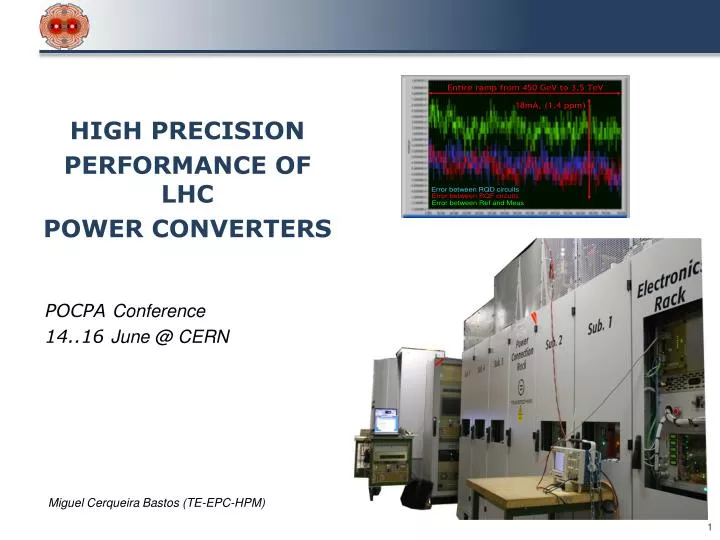
Tracking tests RED(ref): error RQD.A23 (A / B) BLUE: error RB.A12 / RB.A23 GREEN: error RQF.A12 / RQF.A23
Conclusions The LHC requires unprecedented precision for the control of the main circuit currents, mainly due to the division of the machine powering into eight independent sectors. This presentation has shown how the objective has been achieved and how the main challenges have been solved. Thank you for your attention !