Download
1 / 18
240 likes | 549 Views
COMBUSTION EFFICIENCY. THE EFFECT OF COMBUSTION ON THE EFFICIENCY OF THE HEATING APPLIANCE. INTRODUCTION. The combustion efficiency is affected by the manner in which the combustion occurs That is, the air:fuel ratio degree of atomising (liquid fuels) fuel-air mixing flame temperature

E N D
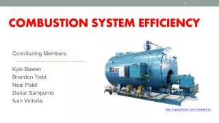
COMBUSTION EFFICIENCY THE EFFECT OF COMBUSTION ON THE EFFICIENCY OF THE HEATING APPLIANCE
INTRODUCTION • The combustion efficiency is affected by the manner in which the combustion occurs • That is, the • air:fuel ratio • degree of atomising (liquid fuels) • fuel-air mixing • flame temperature • flame shape • fuel residence time in the combustion zone • And the amount of heat lost out of the system
AIR:FUEL RATIO • The theoretical air:fuel ratio for complete combustion is known as the “STOICHIOMETRIC” ratio • In practice this ratio does not achieve complete combustion as the degree of mixing is never sufficient to allow every oxygen molecule to come into contact with a fuel molecule • Thus a certain amount of excess oxygen (air) is required to achieve full combustion • The range of excessoxygen required to achieve complete combustion in practical applications is between 1% and 5% depending on the combustion appliance • This implies that an excess air requirement of 5% - 25% is necessary, as there is only ~21% oxygen in air.
AIR:FUEL RATIO • An amount of excess air is necessary for complete combustion • Too much excess air is undesirable as it reduces efficiency by absorbing and carrying away heat • Typically the energy loss due to excess air is in the order of 1,2% for every 10% of excess air by volume
ATOMISING • Applies to liquid fuels only • Is required to generate an even spray of droplets sufficiently small to allow good mixing with the oxygen to achieve complete combustion (usually <50 microns in diameter) • Atomisation is dependent on fuel pressure and viscosity, atomising air or steam pressure, nozzle and burner design • The viscosity can be regulated by controlling the fuel oil temperature
ATOMISING Primary causes of poor atomisation are: • Worn nozzles • Insufficient fuel-oil pressure • Excessive fuel-oil viscosity • Insufficient atomising air or steam pressure • Incorrect nozzle size – excessive turndown • Poor nozzle design • Excessive fuel viscosity (>20 cSt)
FUEL:AIR MIXING • The effectiveness of the burner in achieveing adequate mixing of the fuel and air is crucial to efficient combustion • The burner must provide a stable spray of atomised fuel particles expanding into the combustion air in a manner that will sustain good combustion • The quarl helps sustain the shape of the flame necessary for good combustion
FUEL:AIR MIXING Causes of poor mixing: • Imbalanced air:fuel pressures • Incorrectly set up burners • Worn burner parts • Misaligned burners • Damaged or badly made burner tile (quarl) • Dirty or blocked swirl plates
FLAME CHARACTERISTICS • Heavy fuel oils require more time than light oils and gas to achieve full combustion (respectively 0,1s – 0,01s – 0,001s). Thus the length of the combustion zone is important. • Flame shapes are important as short flames may not provide sufficient residence time for full combustion and “woolly” flames allow unburnt fuel mixture to escape from the side of the flame.
HEAT LOSSES Useful energy (heat) is lost in the following manner: • Poor combustion (0% - 20%) • Insufficient radiance (5% - 15%) • Lost out of appliance from poor insulation (2,5% - 15%) • Up the stack (2% - 10%) • Heating up excess air (0,5% - 3%)
STACK LOSSES • The heat load in the combustion gases is a loss of useful energy • Therefore the stack temperature should be kept as low as possible • The volume of gas should be minimised (excess air) • Stack temperature in a boiler application goes up when the heat transfer surfaces become dirty
MEASUREMENT • It is virtually impossible to set a burner’s air:fuel ratio by eye to ensure complete combustion (minimum CO) and minimum excess air. • The only reliable way is to measure the Oxygen (O2) and Carbon Monoxide (CO< 10 ppm) content in the stack • The burner should be set for minimum O2 in the stack gas without producing more than 10ppm of CO over a range of turn-down
CONTROLS • The only effective way is to install combustion analysers and control the fuel:air mixture automatically • There is a range of such instruments and systems on the market
CONCLUSION • Good combustion requires constant attention to detail, keeping all parts in good working order • Significant savings can be made by controlling and measuring the combustion process