Download
1 / 24
240 likes | 253 Views
Explore the revolutionary concept of a PET detection module for MRI systems, enhancing imaging precision and reducing data fusion complexities. Learn about this groundbreaking technology at the INFN project, its features, and application benefits.

E N D
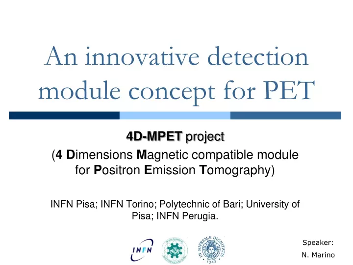
An innovative detection module concept for PET 4D-MPET project (4Dimensions Magnetic compatible module for Positron Emission Tomography) INFN Pisa; INFN Torino; Polytechnic of Bari; University of Pisa; INFN Perugia. Speaker: N. Marino
An innovative detection module for PET Outline • 4DMPET Project at INFN • Readout architecture • Clustering and additional features • Conclusions
4DMPET Project at INFN 1 2 3 4 Project goal A positron emission tomography (PET) scanner detects pairs of γ-rays emitted by a positron-emitting radionuclide inside the body. 3D images of radionuclide concentration are reconstructed by computer. 4DMPET goal: The design of a PET detection module capable of working inside a magnetic resonant imaging (MRI) system.
4DMPET Project at INFN 1 2 3 4 Project goal Why PET/MRI? Nowadays PET and MRI are performed separately in time with distinct machines: • Two images to be merged together • Movements of the patient on the couch • Data corruption from image fusion techniques MRI PET Philips Ingenuity TF PET/MR Combo PET and MRI image fusion
4DMPET Project at INFN 1 2 3 4 Project goal Why PET/MRI? Hybrid PET/MRI systems provide functional and morphological information at the same time: • No image fusion required • Space and costs saving • Better soft tissue contrast • Lower radiation doses Separated PET and MRI rings Hybrid PET/MRI scanner
4DMPET Project at INFN 1 2 3 4 Main features • Silicon Photomultipliers (SiPM) coupled to a single LYSO scintillator crystal: • MRI compatible detectors • x and y coordinates determined with high precision [1] • Time of Flight (TOF): • Reduces image background noise [2] • Depth of Interaction (DOI): • Decreases the uncertainty of the z coordinate [3] • Integrated readout electronics for compact time and energy measurement D = object size ∆t = time resolution
4DMPET Project at INFN 1 2 3 4 Detection module layout • LYSO scintillator slab of 48 mm 48 mm 10 mm (тdecay = 40 ns) • Top and bottom SiPM layers: • 16 x 16 square pixels • 3 mm pixel pitch • microcell size of 50 m • Independent and identical readout boards A B C side view
4DMPET Project at INFN 1 2 3 4 Detection module layout • LYSO scintillator slab of 48 mm 48 mm 10 mm (тdecay = 40 ns) • Top and bottom SiPM layers: • 16 x 16 square pixels • 3 mm pixel pitch • microcell size of 50 m • Independent and identical readout boards F. Pennazio et al., “Simulations of the 4DMPET SiPM Based PET Module”, 2011 IEEE Nuc. Sci. Symp./Med. Imag. Conf.
4DMPET Project at INFN 1 2 3 4 Detection module layout • 4 front-end (FE) mixed-mode ASIC’s (64 channels each) • Cluster processor (CP) ASIC • Laser driver/photodiode receiver/clock reconstruction (LD) ASIC • Fibre-optics (FO) • Communication through LVDS pads • Wire-bonded without package FE FE FO CP LD FE FE top view
Readout architecture 1 2 3 4 Front-end mixed-mode ASIC • Double threshold technique for very high resolution TOF (σLSB=100ps): • Low threshold on single ph-e for an efficient measure of the interaction time • High threshold to discriminate events from noise (SiPM dark count ~ 2 MHz/mm2 @ 27°C ) F. Pennazio et al., “Simulations of the 4DMPET SiPM Based PET Module”, 2011 IEEE Nuc. Sci. Symp./Med. Imag. Conf.
Readout architecture 1 2 3 4 Front-end mixed-mode ASIC • Multiple channels (256 total) • Energy evaluation based on Time Over Threshold (TOT) technique • Two conversion levels: • From SiPM outputs to digital pulses (front-end, AMS 0.35μm SiGe-BiCMOS) • From digital pulses to TOF+TOT information (Time to Digital Converter, UMC 65nm)
Readout architecture 1 2 3 4 Front-end mixed-mode ASIC From SiPM to the TDC OUT IN
Readout architecture 1 2 3 4 Front-end mixed-mode ASIC • Current mode approach for high resolution TOF: • Compatible with CMOS (current mirrors) • Very low Rin for fast response • Wide bandwidth • Programmability for calibration via on-chip DACs: • Time windows (A,B) • High threshold • Discharge current • Signal shaping: • No constraints on the stability and uniformity of the signal • Lower precision required for the TOT measurement
Readout architecture 1 2 3 4 Time to Digital Converter (TDC) Rising and falling edge of events are measured by sampling: • 8 bit systolic counter: • Coarse time Tc • TcLSB = 400 ps • 4 stages delay-locked-loop: • Fine time Tf • TfLSB = 100 ps TOF = Tc + Tf (rising edge) TOT = Tc (falling edge)
Time to Digital Converter (TDC) Readout architecture 1 2 3 4 IN from the front-end • TOF timestamp: 100 ps • TOT timestamp: 400 ps • Nominal σLSB (TOF): 29 ps • Dynamic range: 102.4 ns • Double hit res.: 70 ns • 26 bit digital output word • Other features: • Total pulses count • Missed event flag output: Ch# |flag|TOF|TOT |pulses cnt to the cluster processor OUT missed event
Clustering and additional features 1 2 3 4 Cluster processor ASIC It reduces the amount of data to be sent to the external acquisition system. Three cluster finding algorithms investigated: • Timestamp clustering • Timestamp and spatial clustering • Timestamp and spatial clustering with centroid
Clustering and additional features 1 2 3 4 Cluster processor ASIC Asymmetry in the cluster size on the two crystal faces can be exploited for DOI evaluation: D=detector depth; nup=top face cluster size; ndown=bottom face cluster size. Estimation of the DOI based on the resulting fitted calibration curve has shown a z resolution of 1.3 mm FWHM [4].
Clustering and additional features 1 2 3 4 Additional features (ongoing…) • LD ASIC to minimize the number of communication devices to one optical input and one optical output • Active temperature control: • To reduce the SiPM dark count • To avoid degradations in the electronics performance • Shielding to relax MRI compatibility requirements • Two modes of operation: • Clinical (TOF [coarse + fine], TOT) • Pre-clinical (coarse timestamp only, TOT)
Conclusions 1 2 3 4 Conclusions An innovative PET detection module MRI compatible is under development featuring: • LYSO coupled to 3 mm pitch SiPM on both faces • Large detection area (48 mm x 48 mm) • 8(coarse) + 4(fine) bits for TOF with σLSB of 29 ps • 8 bits energy information based on TOT • DOI with a resolution of 1.3 mm FWHM • Clustering algorithms for smart data reduction
Conclusions 1 2 3 4 Conclusions • 4-channels prototypes of the front-end and TDC ASICs will be submitted during 2012 • Software algorithms for the cluster processor are being studied
References [1] C. Piemonte et al., "Characterization of the First Prototypes of Silicon Photomultiplier Fabricated at ITC-irst", IEEE Trans. on Nucl. Science, Vol. 54, N. 1 February 2007, pp. 236-244. MIC Conf. Record CD-ROM (N41-2),2007. [2] W. Moses, "Recent Advances and Future Advances in Time-of-Flight PET", Nucl Instrum Methods Phys Res A. 2007 October 1; 580(2): 919–924. [3] S. E. Derenzo, W. W. Moses, R. H. Huesman and T. F. Budinger, “Critical instrumentation issues for 2 mm resolution, high sensitivity brain PET”, in Quantification of Brain Function, K. Uemura, N.A. Lassen, T. Jones, et al., Amsterdam: Elsevier Science Publishers, 1993 pp. 25-37. [4] F. Pennazio et al., “Simulations of the 4DMPET SiPM Based PET Module”, IEEE Nuclear Science Symposium / Medical Imaging Conference,M6-5, 2316-2320, Valencia, Spain, 2011. Conclusions 1 2 3 4
FE specifics • Rin = 17 Ω • BW = 250 MHz • Cout = 28 pF (FBK IRST, 625 cells) • Cout = 300 pF (Hamamatsu, 3600 cells)
Timestamp and spatial clustering with centroid Event not contained within the readout face