Download
1 / 10
100 likes | 236 Views
Implementation of high speed digital channel. High Speed Digital System Lab Spring 2009 1 semester project Instructor: Mony Orbach Students: Pavel Shpilberg Ohad Fundoianu. Topics. Definition Theoretical Background Project targets Block diagram Schematic diagram

E N D
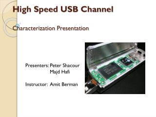
Implementation of high speed digital channel High Speed Digital System Lab Spring 2009 1 semester project Instructor: MonyOrbach Students: PavelShpilberg OhadFundoianu
Topics • Definition • Theoretical Background • Project targets • Block diagram • Schematic diagram • Programmable parameters • Time table
Definition • Examining Stratix card ability of GX (protocols and parameters). • Testing the channel by checking the distortion of signals along the lines using high speed scope. • Implementation of High Speed Serial channel on Stratix 2 GX board.
Theoretical background • Transceiver – used for transmitting/receiving data in the PHY. • PHY – The physical layer of the OSI model consists of PCS, PMA and PMD - physical medium. n m Serial In PCS Digital Section FPGA PMA Analog Section Serial Out m n • Applications – Gigabit Ethernet systems, wireless network routers, fiber optic and communication systems.
Noise In Digital Channel • Amplitude dependent Noise: • CrossTalk: • Capacitive & Inductive Coupling • Shared Signal Return • ISI: Reflections, Oscillations, Inertial Delay. • Timing: Skew, Jitter. • Power Suppluy Noise.
Independent Noise: • Skin Effect • Ohmic Loss • Dielectric Loss
Block diagram • Channel: • rate: 6.1Gbps • I/O : • 8 bit bus • max rate: 710 Mbps Encoding Serilizer 8 8 input 4 Decoding Deserilizer 8 8 PLL output
Schematic diagram Transmitter Receiver 2 PLL 8 8 Output clock Memory Memory HS Scope
Programmable parameters • 8/10 B • Transmit Buffer • Pre-Emphasis • Receiver Input Buffer • Equalizer • PLL/CRU Clock