Download
1 / 6
70 likes | 104 Views
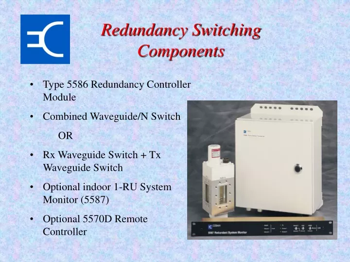
The 5586 Redundancy Controller provides efficient switching components for antenna systems, allowing for robust redundancy control. Monitor and manage your system with optional controllers and alarms for seamless operation.

E N D
Redundancy Switching Components • Type 5586 Redundancy Controller Module • Combined Waveguide/N Switch • OR • Rx Waveguide Switch + Tx Waveguide Switch • Optional indoor 1-RU System Monitor (5587) • Optional 5570D Remote Controller
Low Power Redundancy • The 5W, 10W, 20W, 30W and 40W transceiver can be either mounted on the antenna boom or the antenna pedestal. • Standard mounting kitsupplied is designed to bemounted on the antenna boom • The 5586 RedundancyController and the two5582 Mains Power Suppliesare mounted on the antennapedestal
High Power Redundancy • The 60W or 120W mounting hardware is designed to be mounted to the antenna pedestal with the 5586 Redundancy Controller
5587 Redundancy Monitor • Duplication of the 5586 Redundancy Controller internal switches and LED indicators. • 1RU high assembly • Provides summary alarm for each stream and RF switches • Allows forced switch over between streams • Power is supplied from the Redundancy Controller through the interface cable up to 100m.
Dual 5570 Remote Controller • Full function, permanently-installed, configuration, monitor & control and maintenance. • 2RU high may be “piggy-backed” to the 5587 C-Series Indoor Monitor. • Power is supplied from the Redundancy Controller through the interface cable.
Indoor AC Power 5582 PSU 48V DC 5570D Remote Controller Tx RF Tx RF O/P 5700 Converter Power Control SSPA Rx RF 48V DC M&C 5587 Redundancy Monitor LNA Rx IF Tx IF 5586 Redundancy Controller Rx switch control M&C Cable Blanking Plate OMT Tx switch control LNA Rx IF Termination Modem or other equipment Tx IF 48V DC M&C Rx RF 5700 Converter Power Control SSPA Tx RF O/P 5582 PSU 48V DC Tx RF AC Power Redundant Block Diagram Outdoor Tx RF O/P