Download
1 / 35
350 likes | 508 Views
Forward RPC upgrade at PHENIX. Chong Kim Korea University New Frontiers in QCD - Oct. 27, Yonsei University for the PHENIX collaboration. Contents. Introduction Spin physics at PHENIX Forward muon trigger upgrade Station 3 Geometrical structure Module assembly Module QA

E N D
Forward RPC upgrade at PHENIX Chong Kim Korea University New Frontiers in QCD - Oct. 27, Yonsei University for the PHENIX collaboration
Contents • Introduction • Spin physics at PHENIX • Forward muon trigger upgrade • Station 3 • Geometrical structure • Module assembly • Module QA • Half Octants assembly and QA • Efficiency measurement • Station 1 • Geometrical structure • Module assembly, QA, and installation • Summary and Perspectives
1. Introduction - a. Spin physics at PHENIX 1. a. b. 2. 3. 4. PHOBOS BRAHMS PHENIX STAR • RHIC (Relativistic Heavy-Ion Collider) at BNL, NY, US: • Max. √sNN : 500 GeV (pp) / 200 GeV (AA) • Max. luminosity: 1.5 × 1032cm−2 s−1 (pp) / 2 × 1026cm−2 s−1 (AA) • The only machine capable of colliding high-energy polarized proton beams • PHENIX (Pioneering High-Energy Nuclear Interactions eXperiment): • One of the two ongoing physics experiments at RHIC • Goal: Discover and examine the QGP & Analyze the proton spin
1. Introduction - a. Spin physics at PHENIX 1. a. b. 2. 3. 4. • Spin crisis: • DIS result at 1980s: proton spin is not a simple sum of its constituent quarks • Component-by-component approach: • quarks/antiquarks, gluons, and their angular momenta • →½ = ½ΔΣ+ ΔG + Lz • W measurement at PHENIX: • Full flavor separation of quarks/antiquarks • Measure the polarization of the quark by leptons decayed from W boson ΔΣ = 0.33 ± 0.025 (exp) ± 0.030 (th) ALW: single spin asymmetry p: beam polarization (Max. 70 % for 500 GeV pp) NL(R)(W) : # of events contains the muons from W with corresponding helicity (L or R)
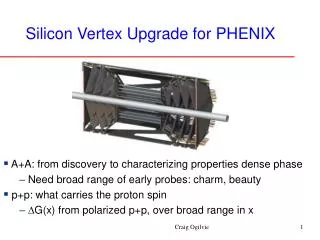
1. Introduction - a. Spin physics at PHENIX 1. a. b. 2. 3. 4. PHENIX detector
1. Introduction - b. Forward muon trigger upgrade 1. a. b. 2. 3. 4. • PHENIX muon arms (before upgrade) • Acceptance • - 1.2 < |η| < 2.2 • - Δφ = 2π • Muon Tracker (MuTR) • - 3 stations of CSCs • Muon ID (MuID) • - 5 gaps of larocci tube in x & y directions • - Total 80 cmthicksteel absorber (plates) • Muon tracking and triggering • - Tracking by hit positions from each station • - Most hadrons are absorbed before • reaching last gap of the MuID • - Current 1st level rejection factor (RF): • ~ 100 (MuID based 1st level trigger) Muon Hadron Muon ID (MuID) Muon Tracker (MuTr)
1. Introduction - b. Forward muon trigger upgrade 1. a. b. 2. 3. 4. Simulated muons into Muon Arms (2000 pb-1, with PYTHIA 5.7) • W measurement at PHENIX muon arms • √s = 500 GeV • σ = 60 mb • L = 1.5 x 1032 cm-2s-1 • →3.0 x 1032 cm-2s-1 (after luminosity upgrade) • Total interaction rate: 9 MHz • DAQ limit: 2 kHz • Required 1st level rejection factor (RF): 4500 • Dedicated trigger system is required: • → Forward muon trigger upgrade After trigger upgrade Current Muon trigger at PHENIX
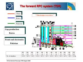
1. Introduction- b. Forward muon trigger upgrade 1. a. b. 2. 3. 4. MuTRG RPC 1 RPC 3 RPC 3 • 35 cm thick Fe absorber • PHENIX forward muon trigger upgrade • Iron (Fe) absorber: reduce hadron background • MuTRG: fast determination of high momentum tracks (tracking) • RPC: provide timing information and rough position information (timing + tracking)
1. Introduction - b. Forward muon trigger upgrade 1. a. b. 2. 3. 4. RPC 1 RPC 3 • Momentum selectivity through online sagitta measurement • Uses MuTr station 1, 2, 3 and RPC station 1, 3 • Implement trigger using fast, parallel logic on FPGA’s • Beam related background rejected by RPC’s timing information
1. Introduction - b. Forward muon trigger upgrade 1. a. b. 2. 3. 4. Module frame (Al) Mylar sheet Cu foil (2 mm) • PHENIX muon trigger RPC • Bakelite double gap RPC • Based on CMS endcap RPC technology and expertise • Fast time response: 1 ~ 2 ns for MIP • Gas mixture: • 95 % C2H2F4 (R134A, base gas for avalanche mode RPC) • 4.5 % i-C4H10 (isobutane, photon quencher) • 0.5 % SF6 (electron quencher) • ~40 % relative humidity
2. Station 3- a. Geometrical structure 1. 2. a. b. c. d. e. 3. 4. Module C 1.96 m RPC3 Module B Module A 3.59 m 0.56 m A half octant (3 RPC modules) Station 3 (16 half octants) RPC 3 RPC 3 • RPC station 3 • One side (N or S) of RPC station 3 is composed of 16 half octants • A half octant is composed of 3 RPC modules (type A, B, and C) • Each moduleis a double-gap RPC which satisfies PHENIX requirements
2. Station 3 - b. Module assembly 1. 2. a. b. c. d. e. 3. 4. Module assembly flow Lay down a Mylar sheet & Cu foil on the bottom module frame Put lower gap & Attach service lines (H.V, gas) Prepare readout strips & Place it on the lower gap Put upper gap on the strip & Attach service lines Put a Mylar sheet on upper gap & Wrap the cu foil Lay down Cu foil on the Mylar sheet (+ frame) Connected gas tube Connect CPE cable to H.V cable on the bottom RPC gap Place lower gap into Cu foil & Connect Polyethylene gas tubes Preparing readout strip (attach signal cables) Close module frame Assembly of module C • Modules for the station 3: ALL (total 96) modules were produced Connect CPE cable to the H.V cable (upper gap) Put upper gap on the readout strip Put readout strip on the lower gap Before wrap the Cu foil Connect gas tubes to the upper gap Fully assembled RPC detector module
2. Station 3 - c. Module QA 1. 2. a. b. c. d. e. 3. 4. RPC cosmic ray test stand - event display Module QA • Before assembly • (Gap QA) • Spacer pop check • Gas leakage check • HV hold • Dark current cosmic ray trigger scintillators RPC readout strip planes • After assembly • (module QA) • Noise rate check • Cosmic ray test cosmic ray trajectory • QA(Quality Assurance) for a detector module: • Before assembly: spacer condition, gas leakage, HV hold and dark current • After assembly (test by cosmic muons): • noise rate, total & strip efficiencie, time resolution & cluster size
2. Station 3 - c. Module QA 1. 2. a. b. c. d. e. 3. 4. Module QA results Noise rate: RPC HV = 9.5 kV, PHENIX RPC FEE threshold = 160 mV Time resolution vs. HV Raw TDC : 1 unit = 100 ns/44 = 2.41 ns Noise rate (Hz/cm2) Efficiency of a module (%) vs. HV with different threshold Cluster size of a module vs. HV with different threshold PHENIX requirements Operation voltage PHENIX requirements Operation voltage
2. Station 3 - d. Half octants assembly and QA 1. 2. a. b. c. d. e. 3. 4. Half octant assembly Route service lines of the module for the assembly Insert prepared modules to the HO frame (3) Insert prepared modules to the HO frame (2) Insert prepared modules to the HO frame Connect & Re-route service lines to the patch pannel View from inside of patch pannel
2. Station 3 - d. Half octants assembly and QA 1. 2. a. b. c. d. e. 3. 4. Integrated result of half-octants QA AT FACTORY Average noise rate: 0.37 Hz/cm2 ↔ PHENIX requirement: <10 Hz/cm2
2. Station 3 - d. Half octants assembly and QA 1. 2. a. b. c. d. e. 3. 4. Integrated result of half-octants QA AT FACTORY RPC3S Average noise rate: 0.25 Hz/cm2 ↔ PHENIX requirement: <10 Hz/cm2
2. Station 3 - d. Half octants assembly and QA 1. 2. a. b. c. d. e. 3. 4. RPC3N - installation (Nov. 11th, 2009) RPC3S - installation (Sep. 22nd , 2010)
2. Station 3 - e. Efficiency measurement Projected hits on RPC3 * Muon tracks at boundaries cut out 1. 2. a. b. c. d. e. 3. 4. 3D Event display Relative efficiency calculation: # of hits on RPC / # of projected track on RPC = # of RPC TDC count / # of Muons RPC coincidence timinghit Count Raw RPC TDC distribution Muon pT (GeV) TDC (106 ns for 44 bins)
2. Station 3 - e. Efficiency measurement 1. 2. a. b. c. d. e. 3. 4. Efficiency vs. runs RUN 11, pp 500 GeV Blue: south Red: north Black: top side Red: bottom side Efficiency (%) Black: module A Red: module B Green: moduleC Before gas mixture optimization: High dark current After gas mixture optimization: Dark current problem resolved
2. Station 3 - e. Efficiency measurement 1. 2. a. b. c. d. e. 3. 4. Efficiency of modules ModuleA Efficiency vs. Height of HO ModuleB ModuleC Average cluster size ( < 2 )
2. Station 3 - e. Efficiency measurement 1. 2. a. b. c. d. e. 3. 4. Good runs selected Efficiency vs. environment • Temperature: almost constant at tunnels • Relative humidity correlated with pressure • Pressure affects RPC efficiency: • ADC gain changed in the chamber • ΔEfficiency / ΔPressure: ~ - 0.219 • (* 30 mbar ~ 12 inches of water) Slope: - 0.219
2. Station 3 - e. Efficiency measurement 1. 2. a. b. c. d. e. 3. 4. Efficiency vs. BBC rate Efficiency (%) Efficiency (%) RPC3 North & South RPC3 North & South, module A, B, andC BBC rate (MHz) BBC rate (MHz)
2. Station 3 - e. Efficiency measurement 1. 2. a. b. c. d. e. 3. 4. Absolute efficiency measurement MuID RPC3 MuTR Hodoscope Location of hodoscope Hodoscope design
3. Station 1 - a. Geometrical structure 1. 2. 3. a. b. 4. RPC 1 90 cm Octant 67 cm RPC1 34 cm • Structure - RPC station 1 • Composed of 16 octants for both sides (8 octants for one side) • Each octant is a double-gap RPC • Two types of octants (A1, A2) for one side: geometrical condition was considered
3. Station 1 - b. Module assembly, QA, and installation 1. 2. 3. a. b. 4.
3. Station 1 - b. Module assembly, QA, and installation 1. 2. 3. a. b. 4. Trigger scintillator 1 2 3 4 5 6 7 8 9 10 RIGHT LEFT Trigger scintillator Intermediate QA result (efficiency) for the south side octants • QA by using cosmic ray • Same QA process to the station 3 case • Average noise rate, Efficiency, Cluster size, etc…
3. Station 1 - b. Module assembly, QA, and installation 1. 2. 3. a. b. 4. • Station 1 status • All octants (total 26, 10 as spares) were assembled • North side installed in Sep. 22nd • QA is underway for the south side octants • South side installation is expected in the end of October • Preparing for the integration RPC1N - installation (Sep. 22nd , 2011)
4. Summary and Perspectives 1. 2. 3. 4. • PHENIX RPCs for the forward muon trigger system: • Provide timing and additional position information • Triggers muons with pT 20 ≥ GeV from W decay • Station 3: • Installation, integration, and commission was completed by early 2011 • Relative efficiency was measured for various conditions: • trigger works fine, but still requires stability test • Absoulte efficiency measurement by using hodoscopes is underway • Station 1: • All 26 octants production completed • North side installed at late Septetmber • South side QA is underway • Installation of south side expected at the end of October • Preparing for the integration
Backup slides Resistive Plate Chamber (RPC) (Φ segmented) B Trigger events with straight track (i.e. Δstrip ≤1) Level 1 Trigger Board Trigger RPC FEE MuTRG Data Merge Amp/Discri. Transmit Trigger 5% Optical MuTRG MRG MuTRG ADTX 1.2Gbps Trigger 2 planes RPC / MuTRG data are also recorded on disk MuTr FEE 95% Interaction Region Rack Room