Download
1 / 21
260 likes | 399 Views
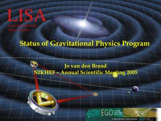
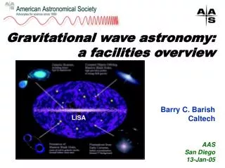
LISA. Laser Interferometer Space Antenna. Gravitational Physics Program Technical implications Jo van den Brand NIKHEF – Staff Meeting, January 2006. http:// www.esa.int/science/lisa. October 3, 2005. VIRGO & Lisa – Technical activities. Linear alignment of Virgo

E N D
LISA Laser Interferometer Space Antenna Gravitational Physics Program Technical implications Jo van den Brand NIKHEF – Staff Meeting, January 2006 http://www.esa.int/science/lisa October 3, 2005
VIRGO & Lisa – Technical activities • Linear alignment of Virgo • Keep mirrors and input beam aligned • Monolithic suspension of Virgo mirrors • Reduce thermal noise • Recycling mirror for Virgo+ • Improve mirror suspension • Lisa electronics • Drag-free control readout
W N EOM Linear alignment of VIRGO interferometer • Phase modulation of input beam • Demodulation of photodiode signals at different output beams • => longitudinal error signals • Quadrant diodes in output beams • => Alignment information • (differential wavefront sensing) • Anderson-Giordano technique • 2 quadrant diodes after arm cavities
Can have 1 normal diode and 2 quadrant diodesat each output port Detection
Present Virgo noise budget Control noise
Present situation • Frascati group is leaving Virgo • Since 01/2006 • Frascati’s responsibilities • Original design of alignment system • Strategy, optics, prototype experiments, … • Design & realization of electronics • Problem • Continue support for alignment electronics • Make new modules / spare modules • Continue development for new requirements
Developments • Present developments • More modules needed • Installation of 9th quadrant diode (maybe 10th) • Spares needed • New Annecy local oscillator boards, compatible with alignment • Phase shifters for standard photodiodes • Possible developments • Substitute Si diodes with InGaAs diodes • Better quantum efficiency • Lower bias voltage • => higher power capability • lower noise • Reduction of electronics noise • Better preamplifier: 5 pA/rtHz -> 1.6 pA/rtHz (?) • DC signals: pre-amplification / pre-shaping • Fast quadrant centering system • (Napoli is working on that) • LA noise limits sensibility (especially at low frequencies)
phase shifter demodulator QD electronics Quadrant diode box Manpower estimate ~ 3FTE from electronics group
Virgo – local control of mirrors Local control of mirrors Present accuracy about 1 micron Feedback systems induce noise Possible application for RASNIC
VIRGO Optical Scheme Input Mode Cleaner (144 m) 3 km long Fabry-Perot Cavities Laser 20 W Power Recycling Output Mode Cleaner (4 cm)
Mirror suspension • High quality fused silica mirrors • 35 cm diameter, 10 cm thickness, 21 kg mass • Substrate losses ~1 ppm • Coating losses <5 ppm • Surface deformation ~l/100
Superattenuators Possible contributions: • Virgo+ will use monolythic suspension • Input-mode cleaner suspension
Monolithic suspension • Fused silica fibers • Bonded to mirror • Reduce thermal noise • Needed for Virgo+ • Realized by GEO600 Weld Silicate (Hydroxy- Catalysis) Bonding
Input beam Transm. beam Refl. beam Input mode cleaner • Mode cleaner cavity: filterslaser noise, select TEM00 mode
LISA - drag free control • SRON • Test equipment for position sensor read-out electronics in on-ground tests of the satellite system • Simulation software modules of the position sensors, used in system simulations • TNO-TPD • Test equipment of the Laser Optical Bench • Decaging Mechanism (TBC) • Bradford Engineering • Cold Gas propulsion (TBC)
LISA key technology • Test-mass position sensing: Capacitive sensing. • Drag-Free control. • FEEP micro-Newton thrusters. NIKHEF and SRON develop ASICS for electronic readout of all LISA signals Low noise, high resolution ADCs NIKHEF 2 – 3 ASIC designers + 2 FTE support
Summary • Linear alignment of Virgo • 3 FTE electronics • Monolithic suspension of Virgo mirrors • 2 FTE EA • Recycling mirror for Virgo+ • 2 FTE EA • Lisa electronics • 2 – 3 ASICS designers • 2 FTE support
Maximized power Optimized mirror centering (0.2 mm) Optimized alignment noise budget
Low-pass filter AC: Gain 200 diff. sig. QD box Shot noise VME non-diff.sig. DC: Gain 1 Preamp. noise ADC noise Non-optimal treatment of DC signals dominated by ADC noise (but were not foreseen as error signals) Scheme of LA electronics