Download
1 / 80
800 likes | 992 Views
Synchronous Sequential Logic Part I. Mantıksal Tasarım – BBM231 M. Önder Efe onderefe@cs.hacettepe.edu.tr. Sequential Logic. Digital circuits we have learned, so far, have been combinational no memory, outputs are entirely defined by the “current” inputs

E N D
Synchronous Sequential LogicPart I Mantıksal Tasarım – BBM231 M. Önder Efe onderefe@cs.hacettepe.edu.tr
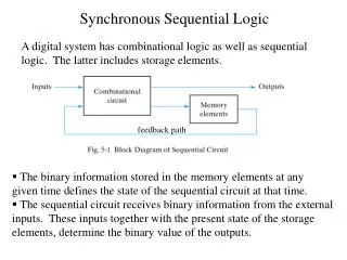
Sequential Logic • Digital circuits we have learned, so far, have been combinational • no memory, • outputs are entirely defined by the “current” inputs • However, many digital systems encountered everyday life are sequential (i.e. they have memory) • the memory elements remember past inputs • outputs of sequential circuits are not only dependent on the current input but also the state of the memory elements.
Combinational Circuit inputs outputs current state next state Memory Elements Sequential Circuits Model current state is a function of past inputs and initial state
Classification 1/2 • Two types of sequential circuits • Synchronous • Signals affect the memory elements at discrete instants of time. • Discrete instants of time requires synchronization. • Synchronization is usually achieved through the use of a common clock. • A “clock generator” is a device that generates a periodic train of pulses.
Classification 2/2 • Synchronous • The state of the memory elements are updated with the arrival of each pulse • This type of logical circuit is also known as clocked sequential circuits. • Asynchronous • No clock • behavior of an asynchronous sequential circuits depends upon the input signals at any instant of time and the order in which the inputs change. • Memory elements in asynchronous circuits are regarded as time-delay elements
Combinational Circuit inputs outputs current state next state Flip-Flops clock Clocked Sequential Circuits • Memory elements are flip-flops which are logic devices, each of which is capable of storing one bit of information.
Clocked Sequential Circuits • The outputs of a clocked sequential circuit can come from the combinational circuit, from the outputs of the flip-flops or both. • The state of the flip-flops can change only during a clock pulse transition • i.e. low-to-high and high-to-low • clock edge • When the clock maintains its value, the flip-flop output does not change • The transition from one state to the next occurs at the clock edge.
Machine • Machine(Inputs {X},States {D},Outputs {Z},OutputFunction {F : XDZ},NextStateFunction {G : XDD})
Assign a NodetoEachState xp/zp xk/zk • Machine is at statedi, inputxkcomes, thenextstatewill be diandtheoutput is zk • Machine is at statedi, inputxpcomes, thenextstatewill be djandtheoutput is zp dj di
Notation • LetIk be an inputsequencewithlengthequalsto k, i.e. Ik= x1x2…xk • f(Ik,di) = z1z2…zk is an outputsequence • g(Ik,di) = di1di2…dik is a statesequence • diIk dik Follower of diaftertheinputsequenceIk
Example - Filloutthe rest A E D C B F
Example • Let I5=10110, find g(I5,C) and f(I5,C) • I5follower of C is F
D FF Q D Positive edge-triggered D Flip-Flop clk C D Flip-Flop • Characteristic equation • Q(t+1) = D Characteristic Table
Other Flip-Flops • D flip-flop is the most common • since it requires the fewest number of gates to construct. • Two other widely used flip-flops • JK flip-flops • T flip-flops • JK flip-flops • Three FF operations • Set • Reset • Complement
Q J C K JK Flip-Flops • Characteristic equation • Q(t+1) = JQ’(t) + K’Q(t) Characteristic Table
Q T C T T (Toggle) Flip-Flop • Complementing flip-flop Characteristic Table • Characteristic equation • Q(t+1) = T Q Q D J C C K
Characteristic Equations • The logical properties of a flip-flop can be expressed algebraically using characteristic equations • D flip-flop • Q(t+1) = D • JK flip-flop • Q(t+1) = JQ’(t) + K’Q(t) • T flip-flop • Q(t+1) = Q(t) T
Whatifwehave Q(t+1) and Q(t), andlookingfor J and K values? Q(t+1) Q(t)=0 X Q(t)=1 Q(t+1)’ Q(t)=1 X Q(t)=0 J= K= Q(t)Q(t+1) J,K
Whatifwehave Q(t+1) and Q(t), andlookingfor D value? Q(t)Q(t+1) D= Q(t+1)
Whatifwehave Q(t+1) and Q(t), andlookingfor T value? Q(t)Q(t+1) T= Q(t+1) Q(t)
Asynchronous Inputs of Flip-Flops • They are used to force the flip-flop to a particular state independent of clock • “Preset” (direct set) set FF state to 1 • “Clear” (direct reset) set FF state to 0 • They are especially useful at startup. • In digital circuits when the power is turned on, the state of flip-flops are unknown. • Asynchronous inputs are used to bring all flip-flops to a known “starting” state prior to clock operation.
data Q D clk C D R reset Q reset Asynchronous Inputs Starting State
Analysis of Clocked Sequential Circuits • Goal: • to determine the behavior of clocked sequential circuits • “Behavior” is determined from • Inputs • Outputs • State of the flip-flops • We have to obtain • Boolean expressions for outputand next state • output & state equations • (state) table • (state) diagram
A Q D x C A’ B Q D C B’ y clk State Equations • Also known as “transition equations” • specify the next state as a function of the present state and inputs • Example A(t+1) B(t+1)
Output and State Equations • A(t+1) = • B(t+1) = • y = A(t+1) A Q D x C A’ B(t+1) B Q D C B’ y clk
Flip Flop Input Equations • Flip-Flop input (excitation) equations • Same as the state equations in D flip-flops
y = • A(t+1) = • B(t+1) = Present state input Next state output A B x A B y 0 0 0 0 0 0 0 0 1 0 1 0 0 1 0 0 1 1 1 0 0 0 0 0 1 0 1 1 1 0 1 1 0 0 0 0 1 1 1 0 0 1 Example: State (Transition) Table 0 0 0 1 0 0 A sequential circuit with m FFs and n inputs needs 2m+n rows in the transition table
1/1 0/0 11 1/0 0/0 0/0 1/0 01 10 1/0 Example: State Diagram 0/0 00 What is this circuit doing? State diagram provides the same information as state table
Analysis with JK Flip-Flops • For a D flip-flop, the state equation is the same as the flip-flop input equation • Q(t+1) = D • For JK flip-flops, situation is different • Goal is to find state equations • Method • determine flip-flop input equations • List the binary values of each input equation • Use the corresponding flip-flop characteristic table to determine the next state values in the state table
JA KA JB KB Example: Analysis with JK FFs x A Q J • Flip-flop input equations • JA = and KA = • JB = and KB = C K B Q Q J D clk C C 1 K y
present State input next state FF inputs A B x A B JA KA JB KB 0 0 0 0 0 1 0 1 0 0 1 1 0 0 1 1 0 1 0 0 0 1 0 1 0 1 1 0 1 1 1 1 1 0 0 0 0 1 0 1 1 0 1 1 0 0 1 1 1 1 0 0 0 1 0 1 1 1 1 0 1 1 1 1 Example: Analysis with JK FFs • JA = Bx and KA = x’+B • JB = x and KB = 1 0 0 0 1 0 1 0 0
Example: Analysis with JK FFs • Characteristic equations • A(t+1) = JAA’ + K’AA • B(t+1) = JBB’ + K’BB • Input equations • JA = Bx and KA = x’+B • JB = x and KB = 1 • State equations • A(t+1) = = • B(t+1) =
1/1 0/0 11 1/0 0/0 0/0 1/0 01 10 1/0 State Diagram 0/0 00 What is the circuit doing?
A x y1 Q TA T C y0 Q Q T D TB B clk C C reset Analysis with T Flip-Flops TA = TB = • Method is the same • Example y1 = A y0 = B
Example: Analysis with T Flip-Flops • Characteristic equation • A(t+1) = TA A • B(t+1) = TB B • Input equations • TA = xB • TB = x • Output equations • y1 = A • y0 = B • State equations • A(t+1) = • B(t+1) =
0 0 01/01 1 1 1 10/10 11/11 1 0 0 State Table & Diagram • A(t+1) = xB A • B(t+1) = x B • y1 = A; y0 = B 00/00
Mealy and Moore Models • There are two models for sequential circuits • Mealy • Moore • They differ in the way the outputs are generated • Mealy: • output is a function of both present states and inputs • Moore • output is a function of present state only
x y Q D C clock C reset S Example: Mealy and Moore Machines Mealy machine • External inputs, x and y, are asynchronous • Thus, outputs may have momentary (incorrect) values • Inputs must be synchronized with clocks • Outputs must be sampled only during clock edges
A x Q T y C Q Q T D B clk C C reset Example: Moore Machines • Outputs are already synchronized with clock. • They change synchronously with the clock edge.
DesignExample - 1 • Implementthefollowingstatediagramwith D FFs. 1/0 0/0 1/1 1 0 0/1
DesignExample - 1 • Implementthefollowingstatediagramwith D FFs. 1/0 0/0 1/1 1 0 0/1
DesignExample - 1 • Implementthefollowingstatediagramwith D FFs. 1/0 0/0 1/1 1 0 0/1
DesignExample - 1 • Implementthefollowingstatediagramwith D FFs. 1/0 0/0 1/1 1 0 0/1 x D Q Z clk
DesignExample - 2 • Design a sequentialcircuitthatcountsup (00, 01, 10, 11,00,…) when x=1, andcountsdown (00,11,10,01,00,…) when x=0. Use JK FFs.
DesignExample - 2 • Design a sequentialcircuitthatcountsup (00, 01, 10, 11,00,…) when x=1, andcountsdown (00,11,10,01,00,…) when x=0. Use JK FFs. x=1 00 01 x=1 x=0 x=1 10 11 x=1
DesignExample - 2 x=1 00 01 x=1 x=0 x=1 10 11 x=1