Download
1 / 44
450 likes | 693 Views
55:035 Computer Architecture and Organization. Lecture 3. Outline. RISC and CISC Comparison Instruction Set Examples ARM Freescale 68K Intel IA-32. RISC and CISC. Reduced Instruction Set Computer Fixed length instructions Simpler Instructions Fewer cycles per instruction

E N D
Outline • RISC and CISC Comparison • Instruction Set Examples • ARM • Freescale 68K • Intel IA-32 55:035 Computer Architecture and Organization
RISC and CISC • Reduced Instruction Set Computer • Fixed length instructions • Simpler Instructions • Fewer cycles per instruction • Load/Store memory access • Register operands only • Probably doesn’t have microcode • RISC is a misnomer – may have many instructions • Complex Instruction Set Computer • Variable length instructions • More complex Instructions • More cycles per instruction • May have “orthogonal” instruction set • Memory and register operands • May have microcode 55:035 Computer Architecture and Organization
ARM • “Advanced RISC Machines” • www.arm.com • Over 90 ARM processors are shipped every second – more than any other 32-bit processor IP supplier • ARM licenses its technology to more than 200 semiconductor companies. • Eight product families 55:035 Computer Architecture and Organization
ARM Example • ARM CortexTM-A8 processor • Intellectual Property (IP) Core • licensed by other companies to create “System On a Chip” (SOC) • Dual, symmetric, in-order issue, 13-stage pipelines • Integrated L2 cache 55:035 Computer Architecture and Organization
31 0 R0 R1 15 General purpose registers R14 31 0 Program counter R15 (PC) 31 30 29 28 7 6 4 0 Status CPSR register N - Negative Z - Zero Processor mode bits C - Carry Interrupt disable bits V- Overflow Condition code flags ARM Register Structure • 15 General Purpose Registers • R14 also link register • By convention • R12 frame pointer • R13 stack pointer • Current Program Status Register • 15 banked registers • copied/restored when going to/from User/Supervisor 55:035 Computer Architecture and Organization
31 28 27 20 19 16 15 12 11 4 3 0 Condition OP code R n R d Other info R m ARM Instruction Format • Load/store architecture (RISC) • Conditional execution of instructions • One or two operands (register) • Destination register • See appendix B 55:035 Computer Architecture and Organization
ARM Addressing Modes where: EA = effective address offset = a signed number contained in the instruction shift = direction #integer, where direction is LSL for left shift or LSR for right shift, and integer is a 5-bit unsigned number specifying the shift amount +/- Rm = the offset magnitude in register Rm can be added to or subtracted from the contents of base register Rn Name Assembler syntax Addressing function W ith immediate of fset: Pre-inde x ed [R n , #of fset] EA = [R n ] + of fset Pre-inde x ed with writeback [R n , #of fset]! EA = [R n ] + of fset; R n [R n ] + of fset Post-indexed [R n ], #of fset EA = [R n ]; R n [R n ] + of fset W ith of fset magnitude in R m : Pre-inde x ed [R n , R m , shift] EA = [R n ] [R m ] shifted Pre-inde x ed with writeback [R n , R m , shift]! EA = [R n ] [R m ] shifted; R n [R n ] [R m ] shifted Post-indexed [R n ], R m , shift EA = [R n ]; R n [R n ] [R m ] shifted Relati v e Location EA = Location (Pre-inde x ed with = [PC] + of fset immediate of fset) 55:035 Computer Architecture and Organization
Memory word (4 bytes) address 1000 LDR R1, ITEM 1004 - ARM Relative Addressing Mode updated [PC] = 1008 1008 - * * 52 = offset * * * * Operand ITEM = 1060 • LDR R1,ITEM • Pre-indexed mode with immediate offset • PC is base register • Calculated offset = 52 • PC will be at 1008 when executed 55:035 Computer Architecture and Organization
ARM Pre-indexed Mode • STR R3,[R5,R6] • Pre-indexed mode • base register = R5 • offset register = R6 1000 STR R3, [R5, R6] R5 Base register * * * 200 R6 1000 Offset register * * 200 = offset * * * * 55:035 Computer Architecture and Organization Operand 1200
ARM Post-indexed Mode w/ WB • LDR R1,[R2],R10,LSL #2 • Use in loop • LSL #2 is logical shift left by 2 bits => x4 • 1st pass: R1 <- [R2] • 2nd pass: R1 <- [[R2] + [R10] x 4] R2 <- [R2] + [R10] x 4 • 3rd pass: R1 <- [[R2] + [R10] x 4] R2 <- [R2] + [R10] x 4 • and so on Memory word (4 bytes) address 1000 6 1000 R2 Base register * * 100 = 25 x 4 * 25 R10 1100 -17 Offset register * * 100 = 25 x 4 * Load instruction: 1200 321 LDR R1,[R2],R10,LSL #2 55:035 Computer Architecture and Organization
ARM Pre-indexed Mode w/ WB • STR R0,[R5, #-4]! • Push instruction • R5 is SP • Immediate offset of -4 is added to [R5] • TOS = 2008 2012 R5 Base register (Stack pointer) 2008 27 27 R0 2012 - Push instruction: after execution of 55:035 Computer Architecture and Organization Push instruction STR R0,[R5,#-4]!
ARM Instructions • All instructions can be executed conditionally • b31-28 of instruction • Most instructions have shift and rotate operations directly implemented in them • barrel shifter • Load/store multiple instructions • LDMIA R10!,{R0,R1,R6,R7} • R0 <- [R10], R1 <- [R10]+4, R6 <- [R10]+8, R7 <- [R10]+12 • R10 <- [R10] + 16 • Condition code set by “S” suffix 55:035 Computer Architecture and Organization
ARM Instructions • Arithmetic • Opcode Rd,Rn,Rm • ADD R0,R2,R4 => R0 <- [R2] + [R4] • ADD R0,R3,#17 => R0 <- [R3] + 17 • immediate value in b7-0 • SUB R0,R6, R5 => R0 <- [R6] – [R5] • ADD R0,R1,R5,LSL #4 => R0 <- R1+[R5]x16 • MUL R0,R1,R2 => R0 <- [R1] X [R2] • MLA R0,R1,R2,R3 => R0 <- [R1]X[R2]+[R3] • ADDS R0,R1,R2 => R0 <- [R1] + [R2] • Sets condition codes NCZV 55:035 Computer Architecture and Organization
ARM Instructions • Logic • Opcode Rd,Rn,Rm • AND R0,R2,R4 => R0 <- [R2] ^ [R4] • BIC R0,R0,R1 => R0 <- [R0] ^ ~[R1] • MVN R0,R3 => R0 <- ~[R3] • BCD Pack Program LDR R0,POINTER Load address LOC in to R0. LDRB R1,[R0] Load ASCI I c haracters LDRB R2,[R0,#1] in to R1 and R2. AND R2,R2,#&F Clear high-order 28 bits of R2. ORR R2,R2,R1,LSL #4 Or [R1] shifted left in to [R2]. STRB R2,PACKED Store pac k ed BCD digits in to P A CKED. 55:035 Computer Architecture and Organization
ARM Instructions 31 28 27 24 23 0 Condition OP code Offset • Branch • Contain 2’s complement 24-bit offset • Condition to be tested is in b31-28 • BEQ LOCATION • BGT LOOP (a) Instruction format 1000 BEQ LOCATION 1004 updated [PC] = 1008 Offset = 92 LOCATION = 1100 Branch target instruction 55:035 Computer Architecture and Organization
ARM Assembly Language Memory Addressing address or data lab el Operation information AREA CODE ENTR Y Statements that LDR R1,N generate LDR R2,POINTER Assembler directives mac hine MOV R0,#0 instructions LOOP LDR R3,[R2],#4 ADD R0,R0,R3 SUBS R1,R1,#1 BGT LOOP STR R0,SUM Assembler directives AREA D ATA SUM DCD 0 N DCD 5 POINTER DCD NUM1 NUM1 DCD 3, 17,27, 12,322 55:035 Computer Architecture and Organization
ARM Subroutines • Example 1 Parameters passed through registers • Branch and Link instruction (BL) Calling program LDR R1,N LDR R2,POINTER BL LIST ADD STR R0,SUM . . . Subroutine LIST ADD STMFD R13!, { R3,R14 } Sa v e R3 and return address in R14 on stac k, using R13 as the stac k p oin ter. MO V R0,#0 LOOP LDR R3,[R2],#4 ADD R0,R0,R3 SUBS R1,R1,#1 BGT LOOP LDMFD R13!, { R3,R15 } Restore R3 and load return address in to PC (R15). 55:035 Computer Architecture and Organization
ARM Subroutines (Assume top of stack is at level 1 b elo w.) Calling program LDR R0,POINTER Push NUM1 – STR R0,[R13,# 4]! on stack. • Example 2 Parameters passed on stack LDR R0,N Push n – STR R0,[R13,# 4]! on stack. BL LIST ADD LDR R0,[R13,#4] Mo v e the sum in to STR R0,SUM memory lo cation SUM. ADD R13,R13,#8 Remo v e parameters from stack. . . . Subroutine – LIST ADD STMFD R13!, { R0 R3,R14 } Sa v e registers. LDR R1,[R13,#20] Load parameters LDR R2,[R13,#24] from stack. MO V R0,#0 LOOP LDR R3,[R2],#4 ADD R0,R0,R3 SUBS R1,R1,#1 BGT LOOP STR R0,[R13,#24] Place sum on stack. – LDMFD R13!, { R0 R3,R15 } Restore registers and return. [R0] Lev el 3 [R1] [R2] [R3] 55:035 Computer Architecture and Organization Return Address Lev el 2 n NUM1 Lev el 1
ARM Program Example – – (j = n 1; j > 0; j = j 1) for – – { ( k = j 1; k > = 0; k = k 1 ) for { (LIST[ k ] > LIST[ j ]) if { TEMP = LIST[ k ]; • Assembly program • Byte sorting program • C program LIST[ k ] = LIST[ j ]; LIST[ j ] = TEMP; } } } ADR R4,LIST Load list p oin ter register R4, LDR R10,N and initialize outer lo op base n ADD R2,R4,R10 register R2 to LIST + . ADD R5,R4,#1 Load LIST + 1 in to R5. – OUTER LDRB R0,[R2,# 1]! Load LIST( j ) in to R0. MO V R3,R2 Initialize inner lo op base register – n 1. R3 to LIST + – INNER LDRB R1,[R3,# 1]! Load LIST( k ) in to R1. CMP R1,R0 Compare LIST( k ) to LIST( j ). STR GTB R1,[R2] If LIST( k ) > LIST( j ), swap STR GTB R0,[R3] LIST( k ) and LIST( j ), and MO V GT R0,R1 mo v e (new) LIST( j ) in to R0. CMP R3,R4 If k > 0, rep eat 55:035 Computer Architecture and Organization BNE INNER inner lo op. CMP R2,R5 If j > 1, rep eat BNE OUTER outer lo op.
Freescale 68K • Freescale Semiconductor • formerly Motorola Semiconductor • www.freescale.com • There are more than 17 billion Freescale semiconductors at work all over the planet. • Automobiles, computer networks, communications infrastructure, office buildings, factories, industrial equipment, tools, mobile phones, home appliances and consumer products • About 20 microprocessor families 55:035 Computer Architecture and Organization
68K • 68K Family • 68000: Introduced in 1979, 16 bit word length and 8/16/32 bit arithmetic, 24 bit address space (16 MB) • 68008: 8 bit version of the 68000 with 20 bit address space • 68010: Version of the 68000 supporting virtual memory and virtual machine concepts • 68020: Extended addressing capabilities, 32-bit, i-cache • 68030: Data cache in addition to the instruction cache, on-chip memory management unit • 68040: Floating-point arithmetic, pipelining, . . . • “ColdFire” family added in 1994 • V1 through V5 cores 55:035 Computer Architecture and Organization
68K Example • ColdFire V5 Core 55:035 Computer Architecture and Organization
68K Register Structure Long word Word Byte • 8 32-bit Data Registers • 8 32-bit Address Registers • A7 is Stack Pointer • Separate Supervisor and User pointers • Users cannot execute privileged instructions • Status Register 31 16 15 8 7 0 D0 D1 D2 D3 Data registers D4 D5 D6 D7 A0 A1 A2 Address A3 registers A4 A5 A6 User stack pointer Stack A7 pointers Supervisor stack pointer 55:035 Computer Architecture and Organization PC Program counter 15 13 10 8 4 0 SR Status register T - Trace mode select C - Carry S - Supervisor mode select V - Overflow I - Interrupt mask Z - Zero N - Negative X - Extend
68K Instruction Format 15 12 11 9 8 7 6 5 0 1 1 0 1 dst 0 src • Three operand sizes: Byte, Word, Long Word • All addressing modes supported (CISC) • One or two operands • See appendix C size OP code 55:035 Computer Architecture and Organization
68K Addressing Modes where: EA = effective address Value = a number given either explicitly or represented by a label BValue = an 8-bit Value WValue = a 16-bit Value An = an address register Rn = an address or a data register S = a size indicator syn tax Name Assem bler Addressing function Immediate #V alue Op erand = V alue Absolute Short V alue EA = Sign Extended WV alue Absolute Long V alue EA = V alue Register Rn EA = R n that is, Op erand = [R ] n Register Indirect (An) EA = [A ] n Autoincremen t (An)+ EA = [A ]; n Incremen t A n – Auto decrement (An) Decremen t A ; n EA = [A ] n Indexed basic WV alue(An) EA = WV alue + [A ] n Indexed full BV alue(An,Rk.S) EA = BV alue + [A ] +[R ] n k Relativ e basic WV alue(PC) EA = WV alue + [PC] or Lab el Relativ e full BV alue(PC,Rk.S) EA = BV alue + [PC] + [R ] k or Lab el (Rk) 55:035 Computer Architecture and Organization
68K Instructions • Format – see appendix C • Opcode src,dst • Opcode src • Arithmetic examples • ABCD, ADD, ADDA, ADDI, ADDQ, ADDX • DIVS, DIVU, MULS, MULU • SBCD, SUB, SUBA, SUBI, SUBQ, • Logic examples • AND, ANDI, EOR, EORI • NBCD, NEG, NEGX, NOP, NOT, • OR, ORI, SWAP 55:035 Computer Architecture and Organization
68K Instructions • Shift examples • ASL, ASR, BCHG, EXT, LSL, LSR • ROL, ROR, ROXL, • Bit test and compare • BCLR, BSET, BTST, TAS, TST • CMP, CMPA, CMPI, CMPMEXG • Branch examples • JMP, JSR, RESET, RTE, RTR, RTS, STOP, TRAP, TRAPV • Memory load and store examples • LEA, PEA, LINK, UNLINK • MOVE, MOVEA, MOVEM, MOVEP, MOVEQ 55:035 Computer Architecture and Organization
68K Assembly Language Move N,R1 Initialization Move #NUM1,R2 Clear R0 – MO VE.L N,D1 Put n 1 in to the LOOP Add (R2)+,R0 SUBQ.L #1,D1 counter register D1 Decrement R1 MO VEA.L #NUM1,A2 Branch>0 LOOP CLR.L D0 Move R0,SUM LOOP ADD.W (A2)+,D0 –1. DBRA D1,LOOP Loopback until [D1]= MO VE.L D0,SUM 55:035 Computer Architecture and Organization
68K Subroutines Calling program – MO VE.L #NUM1, (A7) Push parameters onto stack. – MO VE.L N, (A7) BSR LIST ADD MO VE.L 4(A7),SUM Save result. ADDI.L #8,A7 Restore top of stack. . . . Subroutine – – LIST ADD MO VEM.L D0 D1/A2, (A7) Save registers D0, D1, and A2. MO VE.L 16(A7),D1 Initialize coun ter to n . SUBQ.L #1,D1 Adjust count to use DBRA. MO VEA.L 20(A7),A2 Initialize pointer to the list. CLR.L D0 Initialize sum to 0. LOOP ADD.W (A2)+,D0 Add entry from list. DBRA D1,LOOP MO VE.L D0,20(A7) Put result on the stac k. – MO VEM.L (A7)+,D0 D1/A2 Restore registers. R TS [D0] Level 3 [D1] [A2] Return address Lev el 2 55:035 Computer Architecture and Organization n NUM1 Lev el 1
68K Program Example – – (j = n 1; j > 0; j = j 1) for – – { ( k = j 1; k > = 0; k = k 1 ) for { (LIST[ k ] > LIST[ j ]) if { TEMP = LIST[ k ]; • Byte sorting program • C program • Assembly program LIST[ k ] = LIST[ j ]; LIST[ j ] = TEMP; } } } MO VEA.L #LIST,A1 P ointer to the start of the list. MO VE N,D1 Initialize outer lo op SUBQ #1,D1 index j in D1. OUTER MO VE D1,D2 Initialize inner lo op SUBQ #1,D2 index k in D2. MO VE.B (A1,D1),D3 Current maximum value in D3. INNER CMP .B D3,(A1,D2) If LIST( k ) [D3], BLE NEXT do not exchange. MO VE.B (A1,D2),(A1,D1) In terchange LIST(k) MO VE.B D3,(A1,D2) and LIST( j ) and load MO VE.B (A1,D1),D3 new maxim um in to D3. NEXT DBRA D2,INNER Decrement counters k and j 55:035 Computer Architecture and Organization SUBQ #1,D1 and branch back BGT OUTER if not finished.
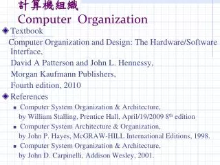
IA-32 • Intel Corporation • www.intel.com • developer.intel.com • Microprocessor used in PCs and Apple computers • Processor Families • Desktop processors • Server and workstation processors • Internet device processors • Notebook processors • Embedded and communications processors 55:035 Computer Architecture and Organization
IA-32 • Intel microprocessor history 55:035 Computer Architecture and Organization
IA-32 Example • P6 Microarchitecture 55:035 Computer Architecture and Organization
IA-32 Example • The centerpiece of the P6 processor microarchitecture is an out-of-order execution mechanism called dynamic execution. Dynamic execution incorporates three data processing concepts: • Deep branch prediction allows the processor to decode instructions beyond branches to keep the instruction pipeline full. • Dynamic data flow analysis requires real-time analysis of the flow of data through the processor to determine dependencies and to detect opportunities for out-of-order instruction execution. • Speculative execution refers to the processor’s ability to execute instructions that lie beyond a conditional branch that has not yet been resolved, and ultimately to commit the results in the order of the original instruction stream. 55:035 Computer Architecture and Organization
IA-32 Register Structure • 8 32-bit Data Registers • 8 64-bit Floating Point Registers • 6 Segment Registers 31 0 R0 R1 8 General purpose registers R7 63 0 FP0 FP1 8 Floating-point registers FP7 16 0 Code Segment CS Stack Segment SS 6 DS Segment ES registers Data Segments FS GS 55:035 Computer Architecture and Organization
IA-32 Register Structure • 32-bit Instruction pointer • Status register • Privilege level • Condition codes 31 0 Instruction pointer 31 13 12 11 9 8 7 6 0 55:035 Computer Architecture and Organization Status register IOPL - Input/Output CF - Carry privilege level ZF - Zero OF - Overflow SF - Sign IF - Interrupt enable TF - Trap
IA-32 Instruction Format 1 to 4 1 or 2 1 1 1 or 4 1 or 4 • Variable instruction length (CISC) • See appendix D bytes bytes byte byte bytes bytes OP code Prefix ModR/M SIB Displacement Immediate Addressing mode 55:035 Computer Architecture and Organization
IA-32 Addressing Modes where: Value = an 8- or 32-bit signed number Location = a 32-bit address Reg, Reg1, Reg2 = one of the general purpose registers EAX, EBX, ECX, EDX, ESP, EBP, ESI, EDI, with the exception that ESP cannot be used as an index register Disp = an 8- or 32-bit signed number, except that in the Index with displacement mode it can only be 32 bits S = scale factor of 1, 2, 4, or 8 Name Assembler syntax Addressing function Immediate V alue Op erand = V alue Direct Lo cation EA = Lo cation Register Reg EA = Reg that is, Op erand = [Reg] Register indirect [Reg] EA = [Reg] Base with [Reg + Disp] EA = [Reg] + Disp displacement * Index with [Reg EA = [Reg] S + Disp S + Disp] displacement Base with index [Reg1 + Reg2 * S] EA = [Reg1] + [Reg2] S Base with index [Reg1 + Reg2 * S + Disp] EA = [Reg1] + [Reg2] S + Disp and displacement 55:035 Computer Architecture and Organization
IA-32 Instructions • Arithmetic examples • ADC, ADD, CMC, DEC, • DIV, IDIV, IMUL, MUL • SBB, SUB • Logic examples • AND, CLC, STC • NEG, NOP, NOT, OR, XOR 55:035 Computer Architecture and Organization
IA-32 Instructions • Shift examples • RCL, RCR, ROL, ROR, SAL, SAR, SHL, SHR • Bit test and compare • BT, BTC, BTR, BTS, CMP, TEST • Branch examples • CALL, RET, CLI, STI, HLT, INT, IRET • LOOP, LOOPE, • Memory/IO load and store examples • LEA, MOV, MOVSX, MOVZX • IN, OUT, POP, POPAD, PUSH, PUSHAD • XCHG 55:035 Computer Architecture and Organization
IA-32 Assembly Language .data NUM1 DD 17 , 3 , 51 , 242 , 113 N DD 5 Assembler directives SUM DD 0 .code MAIN : LEA EBX , NUM1 SUB EBX , 4 MO V ECX , N Statements that generate MO V EAX , 0 machine instructions * STARTADD : ADD EAX , [EBX +ECX 4] LOOP ST AR T ADD MO V SUM , EAX Assembler directives END MAIN 55:035 Computer Architecture and Organization
IA-32 Subroutines Calling program PUSH OFFSET NUM1 Push parameters on to the stack. PUSH N CALL LIST ADD Branc h to the subroutine. ADD ESP ,4 Remo v e n from the stack. POP SUM P op the sum in to SUM. . . . Subroutine LIST ADD: PUSH EDI Sa v e EDI and use MO V EDI,0 as index register. [ECX] Lev el 3 PUSH EAX Sa v e EAX and use as MO V EAX,0 accummulator register. [EBX] PUSH EBX Sa v e EBX and load [EAX] MO V EBX,[ESP+20] address NUM1. PUSH ECX Sa v e ECX and [EDI] MO V ECX,[ESP+20] load count n . Return Address * Lev el 2 ST AR T ADD: ADD EAX,[EBX+EDI 4] Add next n umber. n INC EDI Incremen t index. DEC ECX Decremen t coun ter. NUM1 JG ST AR T ADD Branc h bac k if not done. MO V [ESP+24],EAX Ov erwrite NUM1 in stac k with sum. Lev el 1 POP ECX Restore registers. POP EBX POP EAX POP EDI RET Return. 55:035 Computer Architecture and Organization
IA-32 Program Example – – (j = n 1; j > 0; j = j 1) for – – { ( k = j 1; k > = 0; k = k 1 ) for { (LIST[ k ] > LIST[ j ]) if { TEMP = LIST[ k ]; • Assembly program • Byte sorting program • C program LIST[ k ] = LIST[ j ]; LIST[ j ] = TEMP; } } } LEA EAX,LIST Load list p oin ter base MO V EDI,N register (EAX), and initialize DEC EDI outer lo op index register – (EDI) to j = n 1. OUTER: MO V ECX,EDI Initialize inner lo op index – DEC ECX register (ECX) to k = j 1. MO V DL,[EAX + EDI] Load LIST(j) in to register DL. CMP [EAX + ECX],DL Compare LIST(k) to LIST(j). INNER: JLE NEXT If LIST(k) LIST(j), go to next lo w er k index entry; X CHG [EAX + ECX],DL Otherwise, interchange LIST(k) and LIST(j), leaving MO V [EAX + EDI],DL new LIST(j) in DL. DEC ECX Decrement inner loop index k. NEXT: JGE INNER Repeat or terminate inner loop. DEC EDI Decrement outer loop index j. JG OUTER Repeat or terminate outer loop. 55:035 Computer Architecture and Organization