Download
1 / 29
• 290 likes • 434 Views
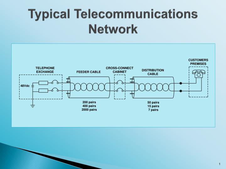
Typical Telecommunications Network. Chorus’ increasingly common roadside electronic cabinets are all effectively small Telephone Exchanges. Telecommunications Circuits. One earth reference on each working circuit – the Exchange earth Maximum voltages normally carried on each circuit

E N D
Chorus’ increasingly common roadside electronic cabinets are all effectively small Telephone Exchanges
Telecommunications Circuits • One earth reference on each working circuit – the Exchange earth • Maximum voltages normally carried on each circuit • 80 Vac ringing voltage (occasionally there) • 48 Vdc always there
Key Mechanisms • Earth Potential Rise (EPR) • Via direct coupling to Exchange earth OR • Insulation breakdown
Induced Voltage • Requires ‘out of balance’ power current (usually earth return current)
Induced Voltage (cont.) • Earth currents return on average at the below depths: ρ = 10 Ω-m 300 m ρ = 100 Ω-m 900 m ρ = 1,000 Ω-m 3,000 m • No insulation breakdown is required to impress voltages onto telecommunications conductors • Mitigation options more limited, and generally more costly
Induced Voltage (cont.) E = C x L x I x K • E = induced voltage (V) • C = coupling factor (mutual impedance) (Ω/km) = fn (ρ,s) ρ = deep earth soil resistivity s = separation • L = length of parallel (km) • I = inducing current (A) • K = shielding factor (≤ 1.0)
Key Impacts • Human hazard • Damage to telecommunications plant • Noise interference
Key Impacts (cont.) • Human hazard • Damage to telecommunications plant • Almost always result from HV phase – earth fault • Maximum impressed voltage readily calculated prior to construction • Consequences major (danger) • Hence ‘predictive’ approach
Key Impacts (cont.) • Noise interference • Arises from ‘normal’ power network operation (not faults) • Maximum impressed voltage very difficult to predict • Causes mal-operation of signalling systems, degradation of call quality (unusable?), slowing down of available broadband speed
Consequences more minor (nuisance) • Rarely a problem • Hence ‘reactive’ approach
Key Power Co-ordination Aspects of Power Networks General • The portion of the earth return current flowing through the soil is the key factor for both EPR and induced voltage hazards • If no voltage is impressed onto telecommunications conductors, there is no problem
Urban • Extensive interbonded MEN systems in urban areas greatly limit EPR magnitude. They do not cause hazard problems. • Can still have EPR hazard from conductive HV power poles and other power earthing systems, that are NOT bonded to extensive interbonded MEN systems. • Induced voltage hazard rare in urban areas due to extensive ‘shielding’.
Rural • Rural EPR levels are very high for HV earth faults
Rural (cont.) • HV earth faults at rural distribution transformers are a particular concern. • EPR typically > 3 kV is transferred onto LV MEN system. • Mains-powered telecommunications equipment may suffer insulation breakdown (to remote earth on incoming telecommunications cable conductors).
Possible solutions: • Separation of HV and LV earths at the distribution transformer. • Petersen coil (or similar) at Zone Substation.
Key Power Co-ordination Aspects of Telecommunications Networks Insulated copper conductor multi twisted pair telecommunications cables • All ‘working pairs’ have a (remote) earth reference provided by the Telephone Exchange earth. • Mains-powered customer’s telecommunications equipment which bridges the power and telecommunication networks is increasingly common.
Typical copper conductor sizes are 0.4 mm and 0.63 mm diameter (0.13 mm2 and 0.31 mm2). • Individual plastic insulated copper conductors in telecommunications cables (since 1970) have been spark tested during manufacture to 1.4 kVrms.
Telecommunications Industry Mitigation Options • EPR Hazard • Shift telecommunications plant to lower EPR area • Replace network plant (e.g. cables) with plant with a higher insulation rating • Shift locally earthed network plant • Install isolation units at customer’s premises
Replace copper cable network plant with fibre optic cables • Special safety practices for telecommunications staff
Induced Voltage Hazard • Reroute parallel telecommunications cables to: • Reduce length of parallel • Increase separation • Install fibre optic cable to roadside electronic cabinet • Reduces parallel to 1/3 of former length
Fibre Optic Cable Networks • Minimal or nil Power Co-ordination impacts • UFB rollout in urban areas is due to be completed in 2020 • However, retirement of urban copper telecommunication cable networks could easily be 10 or more years later
Minor Power Co-ordination issues still apply if the fibre optic cables contain any metallic parts e.g. • Steel strength member • Metallic moisture barrier • Copper tracer wire (for future cable location) • Metal catenary wire (aerial f/o cables) (Ref. PCOG 4.5, 12.2.3)