Download
1 / 29
290 likes | 447 Views
Energy Deposition in the Triplet and TAS issues. francesco.broggi@mi.infn.it francesco.broggi@cern.ch. Outline. Short recall of last year results of a parametric study about the power deposition in the triplet vs. l*. Overview of the works and items investigated this year.

E N D
Energy Deposition in the Triplet and TAS issues CARE-HHH-APD Mini-Workshop IR'07 Frascati 8 November 2007 francesco.broggi@mi.infn.it francesco.broggi@cern.ch
Outline • Short recall of last year results of a parametric study about the power deposition in the triplet vs. l*. • Overview of the works and items investigated this year. • “Back to basics”: Recall of the key parameters and phenomena related to the energy deposition problem. • TAS effect. • IP1-IP5 configurations and differences, effect of the crossing angle and quad field sequence. • MARS-FLUKA comparison. • The actual IP1 layout (see PAC07 paper). • Aperture effect (future work). IR'07 Frascati 8 November 2007
Indications from Power Deposition vs l* The total power deposed into the quads increases, approaching the IP (about 40 % for l* 23 -13 m) The power deposition in Q1 and in its first shells increase almost linearly, approaching the IP (about 100 %) The power deposition in Q3 increase too, but the behaviour is less “linear” The power distribution in the last quad is more spreaded The “hottest” quads is Q2a for l* = 23 m while in the other cases the hottest one is Q3 The highest peak power deposition is in Q2a (and it is almost constant for all the cases studied) The peak power is almost constant for all the situations examined The power deposed in the TAS is almost constant for all the cases IR'07 Frascati 8 November 2007
NO TAS • Parametric study (as function of l*) (PAC 07; C.H.J-P.K., G.S., E.W,F.B.,F.C.) • Adaptive TAS • V (IP1 - ATLAS) • Crossing plane (H/V) and Quad sequence FDDF/DFFD (F.B.) • H (IP5 - CMS) • 2T (ATLAS) • Effect of the Detector Solenoid magnetic field (F.B.) • 4T (CMS) This Year Work • TAS Effect (AT-MCS Note 2007-02, E.W.) • Actual IP1 (ATLAS) configuration • Comparison between FLUKA and MARS (C.H.) • External “TAS” Shield (F.B.) IR'07 Frascati 8 November 2007
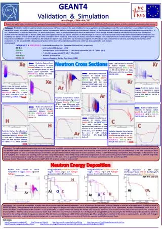
Single diffractive : 12 mb Elastic scattering : 40 mb Inelastic scattering : 60 mb Total cross section : 125 ± 25 mb (P.V. Landshoff arXiv:0709.0395v1) Event cross sections : Particles Source I DTUJET/DPMJEThigh energy hadron-hadron, hadron-nucleus, nucleus-nucleus and photon-nucleus interaction model capable to describe interactions from several GeV/n up to the highest cosmic ray energies, based on the Dual Parton Model. The events from DTUJET for the energy deposition calculation are the inelastic scattering and the single diffractive (72 mb). A conservative value of 80 mbarn is used IR'07 Frascati 8 November 2007
Particles Source II Many type of particles produced with wide spread in energy 82% of the kinetic energy p are the most numerous (75%, 27% p0) Most of the energy is carried by p (20%), (19% by p+,19% by p0 and 14% by p-, 11% by n) p and n have the highest energy per particle
Particles Source III Transverse Momentum (Divergence) of the particles Particles inside the angular acceptance of the beam pipe/TAS are the most energetic. The huge amount of particles with low energy – high transverse momentum goes into the detector or are absorbed/degraded by the beam pipe
Energy Deposition L=8.64 x 1034 cm2 s-1 Beam Power ~ 7760 W Power carried : 60% charged ; 40 % neutral
shield Q1 Tas actions : lower the angular acceptance to the insertion TAS Effect I TAS = Target Secondaries Absorber Last year was dedicated to the parametric study, l* effect with the TAS, constant in aperture, rigidly shifted together with the quads. The beam dynamics changes, when moving the insertion toward the IP. The TAS can/must be adapted too, in order to fit the beam dimensions/separation. (AT-MCS Note 2007-02,E.W.) No / low effect on the peak deposition, only in the total deposition especially in Q1 is affected by the TAS IR'07 Frascati 8 November 2007
TAS Effect II Adapted TAS Studies performed No TAS at all External “TAS”, external shield of Q1 IR'07 Frascati 8 November 2007
Shell 3 (0°) Shell 2 (90°) Shell 1 (180°) Shell 4 (270°) TAS Effect III The TAS does not affect the maximum peak power in the front part of Q1. (Beam pipe 1.75 mm thick considered) r=5.26 cm r=5.26 cm IR'07 Frascati 8 November 2007
TAS Effect IV Scale 10 times higher than Same scale
but the maximum value (front of Q2a) is almost the same either with or without the TAS The value of the maximum of the peak power in Q1 is different TAS Effect V(Peak power) IR'07 Frascati 8 November 2007
With TASExternal ShieldNo TAS Power in Q1(W) 154422 660 TAS Effect(Summary) • TAS is efficient to lower the power deposed in Q1 • The front face of Q1 is well shielded by the external shield too, but the action of the external shields is less efficient on the total power deposition, in addition seems negative for the peak power (to be investigated further, if needed) IR'07 Frascati 8 November 2007
MARS-FLUKA comparison Start Christine’s slides MARS-FLUKA comparison IR'07 Frascati 8 November 2007
Actual and Upgraded Layout IP Beam 2 Beam 1 Possible Upgraded Layout IP Beam 2 Beam 1 Quad Sequence IR'07 Frascati 8 November 2007
Results I(Total Power) The power deposed depends on the magnetic configurations and on the beam crossing plane A symmetry can be found between DFFD_H with FDDF_V and DFFD_V with FDDF_H IR'07 Frascati 8 November 2007
Shell 3 (0°) Shell 2 (90°) Shell 1 (180°) Shell 4 (270°) Results II(Total Power) The Symmetry (with 90° rotation) is more evident IR'07 Frascati 8 November 2007
Results III(PeakPower) The azimuthal distributions refer to the maxima Symmetry is evident but the maxima of the peak power do not occur at the same longitudinal position The most critic point is between the end of Q1 and the beginning of Q2a The case FDDF_H and FDDF_V are quite different, regarding the peak power. CMS is more relaxed
Effect of the detector field I Solenoid parameters ATLAS (IP1)CMS (IP5)2.0 Peak Field (T)4.0 1.1Radius (m) 2.95 5.3 Length (m) 12.4 centered at the IP The power deposed in the quads is the same for both the configuration In the 4T case the bending effect to the lower energy particle is higher, leading to a higher energy deposition in the beam pipe before the quad insertion IR'07 Frascati 8 November 2007
Effect of the detector field II FDDF_H configuration Only a small variation in Q2a
Effect of the detector field III The azimuthal distributions refer to the maxima No effect of the detector solenoid field. The difference between IP1 and IP5 is due to the H or V crossing angle
it is efficient in shielding Q1 The effect of the TAS has been evaluated has low effect on the other quads has low effect on the peak power TAS (and its parameters),for the total power into the quads, especially for Q1 The magnetic field of the quads (peak power) Summary and perspective FLUKA-MARS Comparison useful and is satisfactory The H or V crossing has very different effect, V crossing (ATLAS) is more critical The detector solenoid field in uneffective on the power deposition in the triplet. The power deposition depends on : Evaluate the opening effect, in order to get the full scaling law Not all the variables are independent IR'07 Frascati 8 November 2007
Thanks • The organizing commitee • All the people of the AT-MAS group (Christine Hoa, Jean-Pierre Koutchouk, Elena Wildner, Guido Sterbini, Ezio Todesco, Christine Voellinger, E.Laface, L. Rossi) • The INFN/CERN FLUKA Group (G.Battistoni, A. Ferrari) • Special thanks to F.Cerutti (CERN FLUKA group)for his assistance and suggestions in using FLUKA IR'07 Frascati 8 November 2007
Appendix IAlways specify the volume over which the power density is evaluated Poor statistics IR'07 Frascati 8 November 2007
Appendix IIHypothesis TRACKING • Beam pipe aperture 58.0 - 95.5 mm (Beam screens are taken into account) • Detector Solenoid Field with its fringing field (theoretical) • Hard edge approx. for the quadrupole field Cross section = 80 mbarn (inel.+ single diff. event) • FLUKA • Quad aperture 100.0 mm • Accurate definition of the quadrupole structure (current, insulation, wedges, collars, yokes) • Magnetic field in the quad material (ROXIE) • Cut off for Hadrons 1 MeV • Cut off for electrons/positron 1.5 MeV • Cut off for photons 0.2 MeV • Cut off for neutrons 0.4 eV IR'07 Frascati 8 November 2007
APPENDIX IIIGeometry and materials G10 Insulation (0.2, 0.7, 0.5 mm) S.S. Beam pipe (1.75 mm) S.S. Beam screen with cooling tubes Nb3Sn Current shells (15 mm, 60°) S.S. Pole wedges S.S. Collar (20 mm) Fe Yoke (18 cm) IR'07 Frascati 8 November 2007
APPENDIX IVHead On Collision(qualitative, old case and layout, DFFD) Q1 Q2a Q2b Q3 IR'07 Frascati 8 November 2007
APPENDIX VStatistic errors All these numbers comes out from a Montecarlo computation. It can be seen as a “measurement process”, so it is affect by a measurement error • The statistical error has been evaluated in the previous part of the work (“70-235-80 reference case”). • From different runs with independent random seeds it is about : • 1% for the region binning • 3% medium binning (Bin Volume = 0.5x0.5x50 = 12.5 cm3) • 4% small binning ( " " = 0.25x0.25x50 = 3.1 cm3) IR'07 Frascati 8 November 2007