Download
1 / 68
710 likes | 972 Views
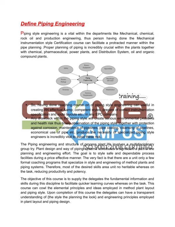
Hospital Building and Campus Piping. 1. Learning Outcomes. Upon completion of this training one should be able to: Identify open loop and closed loop campus-type hydronic water system applications. Understand the variations of primary-secondary piped systems.

E N D
Learning Outcomes • Upon completion of this training one should be able to: • Identify open loop and closed loop campus-type • hydronic water system applications. • Understand the variations of primary-secondary • piped systems. • Explain the importance of properly sized pump impellers. • Explain the importance of sensors in hydronic systems. • Communicate the importance of Life Cycle Costs for • hydronic systems
Hospital Building Occupancy – office and patient areas • Patient areas: 24 hours per day • Office areas: 8 am – 5 pm, Monday - Friday Building Characteristics: • Four story with basement • 140,000 square feet per floor • Standard construction
Hospital – Stand alone operation Larger building Larger pumps Similar applications 5
Medical Complex with Central Plant All buildings served from a single heating and cooling source located in a central plant Hot and chilled water are distributed to each building via piping loops
Medical Complex with Central Plant Similarities Differences • All previous examples can exist in the same or in larger scale • Pumps may be larger • Distribution piping can be different • Location of central plant is critical • Multiple central plants may be tied together
Types of Piping Systems Closed Loop Systems • Chilled Water Systems • Hot Water Systems Open Loop System • Condenser Water Systems • Domestic Hot Water Re-circulation • Domestic Pressure Boosting (future session)
Pump C C C Controller H H H I I I L L L L L L E E E R R R Two Pipe Direct Return Secondary Pumps Supply Common Pipe Return Primary Pumps Expansion Tank Air Separator
Two Pipe Direct Return Common applications • Basis of design for most CHW systems • Small, medium, or large size buildings • Low or high rise • Single or multiple buildings • Single supply temperature
Two Pipe Direct Return Piping Tips • Common pipe design • Tank • Point of No Pressure Change (PNPC) • Warmest water • Air control and relief • 2-way valves • Size • Location
Simplicity First Cost Efficient Over-pressurization Balancing Head requirement Thermally linked Two Pipe Direct Return Advantages Disadvantages
C C C H H H I I I L L L L L L E E E R R R Primary-Secondary-Tertiary Zone C Zone A Zone B Tertiary Pumps Common Pipe Secondary Pump Modulating Control Valves Optional Variable Speed Pump(s) ∆P Sensor Common Pipe Air Separator Primary Pumps Expansion Tank
Primary-Secondary-Tertiary Common applications • Multi-building campuses • Campuses with large diversity • Campuses with buildings of varying heights • Campuses with long piping runs • Campuses with multiple production plants • Campuses with elevation changes
Magna3 MV Load MV Load Tertiary Tertiary MV Zone Zone Load T1 Pumps Pump Common Pipe T2 T3 Small Bypass Maintains Accurate Temperature Reading Secondary Pump(s) Tertiary Bridge Secondary Chilled Water Return Tertiary Loop Piping MV Load MV Load MV Load T1 Magna3 Common Pipe T2 T3 Secondary Pump(s) Tertiary Bridge Secondary Chilled Water Return
C C C H H H I I I L L L L L L E E E R R R Primary-Secondary-Tertiary w/Plate HX Tertiary Pumps Magna3 Expansion Tank Air Separator Plate HX Plate HX Secondary Pump Plate HX Modulating Control Valves Optional VS Pump ∆P Sensor Common Pipe Air Separator Primary Pumps Expansion Tank
Plate Heat Exchanger Flow Return to source From load To load From source
Tertiary Tertiary Zone Zone Pumps Pump Tertiary Loop Piping w/ Plate HX MV Load MV Load MV Load T1 Expansion Tank Air Separator Magna3 Magna3 T2 Plate HX T3 Small Bypass Maintains Accurate Temperature Reading MV Load Secondary Pump(s) Tertiary Bridge MV Load MV Secondary Chilled Water Return Load T1 Expansion Tank Air Separator T2 Plate HX T3 Small Bypass Maintains Accurate Temperature Reading Secondary Pump(s) Tertiary Bridge Secondary Chilled Water Return
Primary-Secondary-Tertiary Piping Tips • When HX are used, additional tanks and air separator devices must be added to tertiary • Controls for secondary and tertiary systems are independent
Hydraulic isolation Thermal isolation Horsepower reduction Operational cost savings System performance optimization Additional piping Additional control valves First cost Over-pressurization of near zones unless plate hx is used More pumps Primary-Secondary-Tertiary Advantages Disadvantages
Open Piped Systems Chiller Piping • Condenser water piping • Condenser water with economizer
Supply Secondary Pump(s) Tower Optional Plate Heat Exchanger And Pump Primary Pump(s) Evaporator Return Condenser Expansion Tank And Air Separator Optional Sediment Separator Condenser Pump(s) Chiller Condenser Water Piping
Supply Secondary Pump(s) Tower Loads Primary Pump(s) Head Pressure Control Valve Return Evaporator Expansion Tank And Air Separator Condenser Sediment Separator Condenser Pump(s) Heat Exchanger Condenser Water w/ Economizer
Supply Secondary Pump Cooling Tower Loads Primary Pump Head Pressure Control Valve Evaporator Return Condenser Air Separator And Exp Tank Condenser Pump Chiller Sediment and Air Separator Water Cooled Chiller Piping
Water Cooled Chiller w/ Water Economizer Supply Secondary Pump Cooling Tower Loads Primary Pump Head Pressure Control Valve Valve Position: Open Evaporator Return Condenser Air Separator And Exp Tank Sediment Separator Chiller Condenser Pump Chiller Operation Economizer Condenser Pump Heat Exchanger
Water Cooled Chiller w/ Water Economizer Supply Secondary Pump Cooling Tower Loads Primary Pump Valve Position: Closed Evaporator Sediment Separator Return Air Separator Exp Tank Condenser Condenser Pump Chiller Economizer Mode Economizer Condenser Pump Heat Exchanger
ASHRAE Standard 90.1-2010 Prescriptive Path 6.5 Prescriptive Path 6.5.1 Economizers 6.5.1.2 Water Economizer Required for specific OA temperature and humidity 6.5.1.2.2 Maximum Pressure Drop Feet of head for water to water heat exchanger < 15’ acceptable ≥ 15’ head secondary loop required so this pressure drop is not seen by the circulating pump
Water Cooled Chiller w/ Water Economizer Supply Secondary Pump Cooling Tower Loads Primary Pump Valve Position: Closed Evaporator Sediment Separator Return Condenser Air Separator And Exp Tank Condenser Pump Chiller Economizer Mode Economizer Condenser Pump Economizer Chilled Water Pump Heat Exchanger
Best Practice Design • Why • Constant speed pump • Variable speed pump Optimize Pump Impeller
Best Practice Design Why Equipment over-sizing Cost penalty Mandate Optimize Pump Impeller
Best Practice Design Constant speed pump • Trim the impeller • Utilize the affinity laws • Follow the system curve • Save operating cost • First costs 35
Best Practice Design Variable speed pump • Impeller optimization • Follows affinity laws • First cost impacts • Does not correct for poor engineering • Over-sized pumps minimize turndown ratio • Over-sized pumps and motors operate at lower efficiencies
Best Practice Design Primary Piping for Hot Water Systems • Pump out of a boiler • Keep the boiler at the lowest possible pressure • Remember NPSH! P2 P1 Boiler 1 Boiler 2
Best Practice Design Primary Piping for Chilled Water Systems • Pump into a chiller • Largest pressure drops after the pump Chiller Chiller Chiller Primary Pumps
Condenser Water Piping Condenser Water Piping Tips • Installation • Maintenance
Condenser Water Piping Condenser Pump Cooling Tower Evaporator Condenser Chiller Sediment and Air Separator • Installation • Pump suction flooded • Watch NPSHa 40
Condenser Water Piping Cooling Tower Evaporator Condenser Obstacle Chiller Condenser Pump • Operation • Air pockets • End of curve 41
Condenser Water Piping Cooling Tower Condenser Pump Evaporator Condenser Sediment/Air Separator And Relief Valve: Alternate Locations Chiller • Maintenance • Strainers • Air vents 42
Best Practice Design System Bypass Options Secondary CS Pump(s) Supply Chiller 2 Chiller 3 Chiller 1 Pump Controller Common Pipe Return
Best Practice Design System Bypass Options • Locate bypass near end of system • Locate bypass near end of major loops • Selectively leave 3-way valves • Bypass with pressure activated control • Variable speed considerations
120 100 % Speed 110 100 90 80 70 Head 60 30% Speed 50 40 30 20 10 0 % Flow 60 70 80 90 100 0 10 20 30 40 50 Best Practice Design • Below 30% speed: CS, but still VV Effect at program minimum VFD speed
Pump 1 Variable Speed: 500GPM @ 100 Ft 1000 GPM Wrong! Pump 2 Constant Speed: 500 GPM @ 100 Ft 1000 GPM Best Practice Design Mixing CS and VS Pumps
∆P Sensor Pump Controller Best Practice Design Sensor Location Secondary Pumps Supply Chiller 3 Chiller 1 Chiller 2 VFDs Return Primary Pumps
Best Practice Design Sensor Location • The Traditional Way • Hydronically, the farthest load • Typically the largest, farthest load • Maximize the variable head loss • Multiple sensors are a benefit
Best Practice Design • Optimized solution not only for the pumps, but for the total system conditions • Proportional pressure, calculated • Proportional pressure, measured • FLOWADAPT and AUTOADAPT 49
Best Practice Design • Uncontrolled • Constant pressure • Proportional pressure (calculated) • Proportional pressure (measured) • Temperature control 100 80 60 40 20 0 1. Effect in % H 2. 3. 4. 5. 0 20 40 60 80 100 Flow in % 25% 100% Q Get Additional Energy Savings 50