Download

1 / 22
300 likes | 764 Views
Introduction to Capillary Electrophoresis Technology. Outline. Overview of Capillary Electrophoresis (CE) Modes of CE operation Development History – Parallel CE with UV Absorbance Detection cePRO 9600 ™ Technology Benefits of Parallel CE Technology Summary. Inlet (injection) Side.

E N D
Outline • Overview of Capillary Electrophoresis (CE) • Modes of CE operation • Development History – Parallel CE with UV Absorbance Detection • cePRO 9600™ Technology • Benefits of Parallel CE Technology • Summary
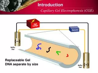
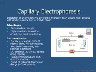
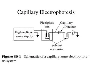
Inlet (injection) Side Outlet Side Introduction to Capillary Electrophoresis (CE) • Separation by applying high voltage across fused silica capillary filled with conductive buffer • Capillary can be filled with: • Aqueous buffer (CZE) • Aqueous-based buffer with surfactants (MEKC, MEEKC) • Gel matrix (CGE) • Detection can be by UV absorbance, fluorescence, mass spectrometry, conductivity
Electro osmotic Flow (EOF) • In a bare, uncoated silica capillary, a double layer of ions forms at pH > 4 • The outer mobile layer is driven to cathode (detector), creating bulk flow • This bulk flow can carry both positive and negative analytes to detector • EOF must be eliminated for some applications such as DNA/protein separations
-- - - + ++ + N - -- + ++ Bulk Flow: EOF + Vacuum Time UV Capillary Zone Electrophoresis (CZE) • Application of high voltage across capillary filled with aqueous conductive buffer • Narrow bore, fused silica capillaries (50-75 mm i.d., 192 mm o.d.) • Electroosmotic flow (EOF) provides bulk flow towards cathode (detector) at pH > 4 • Application of vacuum can provide additional bulk flow to detector at all pH values • Migration time dependent on analyte’s charge-to-mass ratio; neutral compounds migrate with bulk flow
Least Hydrophobic Most Hydrophobic EOF + - Time Micellar Electrokinetic Chromatography (MEKC) • Separation based on the partition of analytes between the aqueous phase and charged micelle phase with ionic headgroup and hydrophobic core (e.g., SDS) • More hydrophilic/lipophilic compounds favor the micelle phase and migrate slower • A retention window is created with order of migration: EOF marker (e.g., DMSO), analyte, micelle marker (e.g., dodecylbenzene) • Separation of neutral/charged compounds based on hydrophobicity/charge state • MEKC is the “CE version” of reversed-phase HPLC Figure taken from presentation at http://franklin.chm.colostate.edu/cshenry/C531.ppt
- - - - - - + - - - - UV Capillary Gel Electrophoresis (CGE) • Capillary is filled with conductive gel sieving matrix • Size-based separation of species possessing a constant mass-to-charge ratio (e.g., denatured SDS-protein complexes, ssDNA oligonucleotides, dsDNA/dsRNA) • Smaller sized species migrate faster, larger molecules move slower • EOF needs to be eliminated to achieve maximum separation performance • CGE is “CE version” of slab gel electrophoresis (PAGE)
Vacuum (-0.2 psi) Sample Plug Vacuum Injection of Samples in CE • Advantages: • No injection bias of sample molecules due to sample charge • Sample matrix does not influence amount of sample injected • Disadvantages: • Little to no sample “stacking” effects = poorer sensitivity • More difficult to reproducibly control • Difficult to inject samples into high viscosity buffers (e.g., gel matrix) Vacuum injection is suitable for most CE applications: pKa, log P, chiral separations, protein sizing
Capillary with high conductivity buffer Capillary with high conductivity buffer + + Cl ˉ Cl ˉ Cl ˉ Cl ˉ Cl ˉ - - - - - - - - - - Electrokinetic (Voltage) Injection of Samples in CE Interface Low conductivity sample (e.g. H2O) High conductivity sample (e.g. Tris-HCl) • Advantages: • “Stacking”: sample ions focus at low conductivity sample/high conductivity buffer interface • Stacking of sample ions can greatly increase detection sensitivity • Disadvantages: • Injection bias: only ions possessing appropriate charge will be injected • Matrix effects: sample will not be injected in presence of salts Electrokinetic injection is used for DNA analysis
Multiplexed (Parallel) CE-UV Technology • 24 or 96 capillaries are arranged in a linear array at detection window • UV light is passed through capillary array and imaged onto photodiode array detector • Capillary inlets are arranged 8 x 12 for direct sample injection from 96-well micro plates • Capillary outlets are bundled to a common reservoir connected to pumping system • Sample injection by vacuum or voltage • 24 or 96 individual CE separations are performed in parallel
W lamp (idle) camera lens fan window diode array Hg lamp light shield battery samples flush/ fill Dr. Edward Yeung’s Laboratory Prototype (“Gray Box”) • Manual capillary filling (by syringe); manual sample injection (by gravity or voltage) • Proof-of-concept demonstrated (Gong and Yeung, Anal. Chem.1999, 71, 4989-4996) • Patent protected, core technology exclusively licensed from ISU to CombiSep
MCE 2000System • First generation commercial 96-capillary array CE-UV instrument • Fixed wavelength UV or visible detection; vertical optics design • Vertical z-stage accommodates a single 96-well plate • User manually exchanges waste, buffer and sample plates during analysis
cePRO 9600™ System • Second generation 96-capillary array CE instrument • Horizontal optics design; slightly improved detection sensitivity • Automated XYZ stage holds up to four 96-well plates (1 waste, 1 buffer, 2 sample) • System can be interfaced to a robotic arm for unattended well plate exchange
HV Power Supply Capillary Array Detection Window Capillary Array Cartridge Optical Platform Housing Lamp Housing Syringe Pump Inside View of the cePRO 9600™ Instrument
96-Capillary Array Viewed from Detector Position Capillary Outlets (12 Bundles of 8 Capillaries) Capillary Inlets (Arranged in 8 x 12 Format) Detection Window (Polyimide coating removed)
Capillary Array Inlets Viewed from Below • Capillaries are arranged side-by-side with tungsten electrodes • Direct injection by vacuum or voltage from 96-well plates • Recommended minimum sample volume: 40 mL
Image of 96-Capillary Array on PDA Detector • Continuous measurement of UV intensity simultaneously in all 96 capillaries • Absolute light intensity does not have to be equal as the relative absorbance is measured in each capillary
cePRO 9600 Performance Specifications • Detection • Fixed wavelength, using D2 (193 nm – 400 nm), Zn (214 nm) Cd (228 nm) or Hg (254 nm) lamps and narrow band pass filter • Capillary Array Dimensions • 50 mm or 75 mm i.d., 200 mm o.d. • Effective lengths 30 cm to 60 cm; 20 cm fixed length from detector to outlet • Sample Injection • Vacuum or Electrokinetic; 40 mL minimum sample volume; nL volumes injected • Operational Conditions • Typical total operating current < 4 mA (<40 mA/capillary) • Operating voltage to ± 16 kV; field strength to 250 V/cm • Forced air cooling at RT or at ~16 ºC • Detection Limits • Low mM concentrations for a standard injection volume • Common MCE-UV Separation Modes • Capillary Zone Electrophoresis (CZE) • Microemulsion Electrokinetic Chromatography (MEEKC) • Capillary Gel Electrophoresis (CGE)
Robotic Arm Integration for Unattended Analysis • A Thermo CRS Catalyst Express robotic arm was integrated to facilitate unattended well plate exchange between multiplexed CE-UV runs. • Using this configuration, 96 samples were analyzed in parallel over 24 pH values in 8 h (2304 total separations) to determine their respective pKa values without user intervention. Only 10 mg of compound was required for the analysis. • Use of a robotic arm interfaced with MCE-UV and a well plate hotel allows for long term and/or overnight operation.
Benefits of Multiplexed CE-UV for Pharmaceutical and Biotechnology Applications • High Throughput - simultaneous monitoring of up to 96 individual CE separations • UV absorbance (214 nm, 254 nm) provides more universal analyte detection • Variation of buffer conditions (pH, ionic strength, additives) in different capillaries for accelerating methods development • Multiple applications can be performed using the same instrument platform • Minimal sample consumption (g amounts required; ng amounts consumed) • Sample impurities can be resolved when performing assays • Low cost per sample
Application Specific System Solutions Oligo PRO™ System pKa PRO™ System • Parallel CGE system • ssDNA/ssRNA purity analysis • dsRNA duplex analysis • High pressure pumping system (500 psi) • Customized, application specific software • 24 or 96 capillary configurations • Parallel CZE/MEKC system • pKa and pI measurements • Dedicated software for pKa data analysis • Also for log P analysis; chiral separations • 24 or 96 capillary configurations
Summary • Multiplexed CE-UV technology can be applied to a broad range of high throughput applications spanning pharmaceutical and biotechnology markets • The ability to perform CE in parallel with 24 or 96 capillary arrays provides a significant improvement in throughput and laboratory efficiency at a fraction of the cost for alternative technologies • Many methods previously developed for single capillary CE instruments can be successfully transferred to a multiplexed format • The multiplexed CE format provides the flexibility to simultaneously vary separation conditions to speed development processes • Multiplexed CE-UV provides a significant business advantage: low cost per sample, lower turnaround times, small sample consumption, decreased reagent consumption, and increased throughput