Download
1 / 69
690 likes | 825 Views
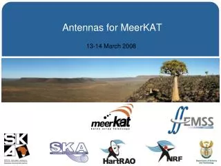
Developing a low cost dish for MeerKAT. Willem Esterhuyse Subsystem manager: Antenna Structures willem@ska.ac.za 083 447 1615. Overview. Introduction Partners Main Specs Philosophy Schedule Progress Analyses (CFD/FEA) Detail Design Manufacturing/Construction Acceptance/Verification

E N D
Developing a low cost dish for MeerKAT Willem Esterhuyse Subsystem manager: Antenna Structures willem@ska.ac.za 083 447 1615
Overview • Introduction • Partners • Main Specs • Philosophy • Schedule • Progress • Analyses (CFD/FEA) • Detail Design • Manufacturing/Construction • Acceptance/Verification • Life after XDM (Cost optimization and KAT7 – composite dish) • Conclusion
Introduction (1) • This presentation from mechanical design perspective • Antenna performance/Feeds – EMSS (LJ du Toit/ Isak Theron)
Introduction (2) - XDM • 15 meter PF antenna on ALT-AZ mount with feed rotator • One-piece composite reflector that is structural • Simple back-up structure • No Panels to align • Weight saving • Concrete pedestal • Pedestal only 30% of foundation (bedrock) volume • Aim – Antenna for KAT that is relevant to SKA. • Technical/Cost • Development Subcontracted (time constraints) • IST Dynamics (PTY) LTD • Single line of responsibility (time, risk) • MMS subcontracted for dish
Partners - IST • Prototype development subcontracted to IST Dynamics. Shared IP. • IST Dynamics • Prime contractor – IST exists for more than 25 years • High tech electro-mechanical systems + software • Military is biggest client • ISO 9001 and ISO 14001 • www.ist.co.za, follow link to dynamics
Partners - MMS • MMS • Subcontracted by IST • Dish construction and design • Exceptional experience in Composite design and manufacture • Existing for more than 20 years • For more detail, see www.mmstechno.co.za
Philosophy • Highest risk (technical and cost) – Reflector • Preferably one-piece reflector (no alignment of panels) • This requires manufacturing on site • Tooling costs very high for steel, much lower for composites • Composites attractive for smaller quantities (limited budget) • Composites offer other advantages as well • Lighter for same stiffness/strenght • On site manufacturing easy (minimal equipment required) • Better thermal performance • Going to offset antennas not significant impact on reflector • Preferably very simple backup structure (if any) – structural reflector • Pedestal – concrete (30% of foundation concrete) • Revisited in cost optimization study
Schedule (KAT Antenna Structures) • XDM • Contract Signed 24 April 06 (DONE) • PDR 20 June 06 (DONE) • CDR 28 Aug 06 (DONE) • FATS 12 Feb 07 (DONE) • Installation Completed 16 May 07 (DONE) • ATP Completed 17 July 07 (DONE) • Documentation Completed 17 July 07 (DONE) • KAT7 & MeerKAT • 12m Design/Cost optimization Sept 07 – Dec07 (DONE) • KAT7 Tender Jan 07 (Progress) • KAT7 Contract award April 07 • KAT7 Array Completed Nov 09 • MeerKAT Contract award Jan 2010 • MeerKAT Array Completed Nov 2012
ANALYSES - CFD • Detailed CFD (Computational Fluid Dynamics) analyses to determine pressures on dish as result of wind loading (for use in FEA analyses) • Results compared to published results – good correlation • Results compared with limited experimental data – good correlation
Analyses – FEA – Modes Mode 1: 4.2 Hz side to side Mode 2: 4.4 Hz dish “flaps” Mode 3: 4.7 Hz nodding
Detail Design/Manufacture - Dish • Very simple backup structure • Dish is structural (approx. 5 Tons) • Symmetric, to eliminate curing distortions • Manufacturing (see pictures later): • Machine patterns (composite pattern material) • Make composite moulds of the patterns • Combine composite moulds to create dish mould • Innovative and cheap honeycomb structure (off the shelf honeycomb cores very expensive). • Vacuum Infusion process used for molding entire dish as a unit
Detail Design/Manufacture - Dish Typical dish lay-up
Detail Design – Drives/Controls • Azimuth axis • 1 spring - loaded drive • 2 deg/s, 460 degree travel • Elevation axis • 1 spring - loaded drive • 1 deg/s, 0 to 95 degree elevation range • Elevation axis is BALANCED • Light dish (composites) makes this possible with minimal use of counter weights • Feed rotator axis • 380 degree travel
Verification/Acceptance • Completed • Achieved all design goals • Dish tested at 1.42 and 12 GHz • Dish accuracy around 1.7mm RMS • (Confirmed with Theodolite and Photogrammetry measurements) • Improve? – pattern from Al, mold. • Al Flame sprayed surface works well • Pointing – 25 arcsec RMS (optically) • Improve? – probably 2 drives • Thermal performance – thermocouples molded into dish front and rear to verify analyses assumptions.