Download
1 / 18
180 likes | 641 Views
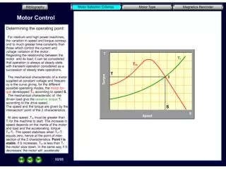
DC Motors, Stepper Motors, H-bridges. DC Motors Stepper Motors Motor Control Circuits Relays H-bridges. AC versus DC Motors. AC motors are not very flexible w/o a transmission They can only turn in one direction

E N D
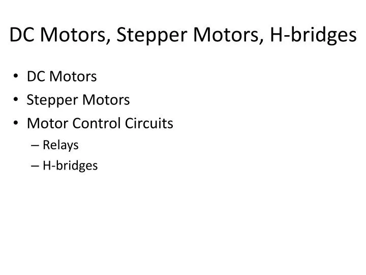
DC Motors, Stepper Motors, H-bridges • DC Motors • Stepper Motors • Motor Control Circuits • Relays • H-bridges
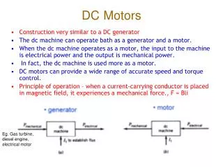
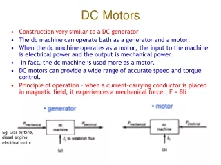
AC versus DC Motors • AC motors are not very flexible w/o a transmission • They can only turn in one direction • The speed is controlled by the design of the motor and the frequency of the AC current source (60Hz) • DC Motors can be operated more flexibly • They can turn in either direction based on the polarity of the applied voltage • The speed is controlled by the magnitude of the voltage
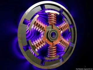
DC Motors • A DC motor has coils on a rotating electromagnetic armature in a fixed or variable magnetic field • A commutator connects the DC power source in sequence to the coils in the armature as it turns • Commutator end view: Fixed /Variable Field Magnet + - Electromagnetic Armature Coil (1 of Several) Brushes Commutator Fixed/Variable Field Magnet - +
DC Motors • A continuous voltage across the brushes will keep the motor turning in either one direction or the other depending on the polarity • A higher voltage across the brushes will make the motor turn faster • A lower voltage across the brushes will make the motor turn slower • The commutator sparks as it turns creating EMI or possible explosion hazard
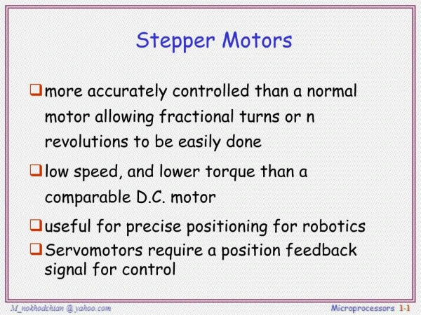
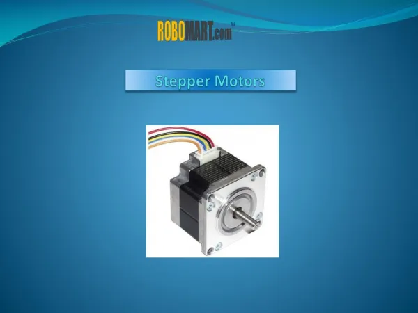
Stepper Motors • A stepper motor is a DC motor that has fixed magnets on the armature • It does not use a commutator to automatically energize/de-energize different magnetic coils • The ends of the coil windings in the field are alternately energized and de-energized by an external control circuit in a desired sequence • The order and dwell time of the voltage to each coil controls the direction and the speed
Stepper Motors • A stepper motor can be held in a fixed position by pausing the sequence and keeping one coil energized for the duration of the hold time • Hence, a stepper motor can be used in similar applications as a servomotor (studied in CS341) • It can be moved to and held in a desired position • It can be rotated continuously at a controlled speed • The control is all externally implemented
Types of Stepper Motors • Many possible geometric arrangements of the: • Fixed magnets on the armature • Electromagnetic coils in the field around the armature • References: http://homepage.cs.uiowa.edu/~jones/step/types.html • Our Mercury Motor is a Bipolar Stepper Motor
Stepper Motors - Heat • Stepper motors are designed to operate at a high temperature and can get hot (~ 80 deg C) • If this causes a problem, try the following: • Lower the voltage (But I found the Mercury motor will not step/hold reliably at 9 VDC versus 12 VDC) • Turn off the power to the coils when not in use (Expect that the motor will slip out of position) • Mount the motor on a heat sink to dissipate heat • Use a fan to create air flow over motor / heat sink
Motor Control Circuits • A motor control circuit: • Provides power to the motor coils in either polarity • Allows the external logic to control direction/speed • There are two basic types of motor controllers • Electromechanical relay based controllers • Semiconductor based controllers (H-bridges) • Each type has its advantages and disadvantages • We’ll use our elevator motors as an example
Relay Motor Control Circuit • Two relays can be used to provide on/off and up/down control for our elevator DC motor To Arduino Output Pins & Ground Up Down NO - + Red + 9 VDC To Motor Power Supply NC Ground Black NC + - Black NO Yellow Safety switch: Stops “up” when the car hits switch
Relay Motor Control Circuit • Advantages • Uses simple, robust electromechanical devices • Can handle high voltages and large currents • Disadvantages • Requires periodic maintenance (cleaning contacts) • Relatively slow due to inertia in mechanical parts • Contact make/break/bounce sparks creating EMI or possible explosion hazard • Example: Used under the hood in cars
Relay Motor Control Circuit • A DC motor such as the drive motor for our elevator system requires one circuit per motor • The direction is determined by one relay or the other being turned on - closing normal open (NO) contact • A bipolar stepper motor such as the Mercury Motor requires two circuits per motor • Each coil is turned on and off in a selected direction in sequence to change the position continuously • One coil can be left on in a selected direction to hold in a desired position
Bipolar Motor - Relay Shield Wiring Don’t Connect Positive Sides + 12 VDC Stepper Motor Coil A Stepper Motor Coil B Arduino Uno NO NO NO NO Black Brown Orange Yellow NC NC NC NC Connect Grounds Relay Coil 0 Relay Coil 1 Relay Coil 2 Relay Coil 3 • Clockwise • + - • + • + - • - + • Counter CW Pin 7 D0 Pin 6 D1 Pin 5 D2 Pin 4 D3
H-bridge Motor Control Circuit • An electronic version of previous relay circuit • Can be implemented with individual components http://www.youtube.com/watch?v=A_JNjAFo1f4 • Can use an L298 H-bridge component • Two independent H-bridge circuits per component • Needs external “snubber” or “flyback” diodes
H-bridge Motor Control Circuit • Half of an L298 H-bridge can be used to provide on/off and up/down control for a DC motor +9 or 12 VDC Vs Snubber Diodes Red Up Down +5 VDC Vss Pin 4 Pin 2 Pin 9 - + Input 1 L298 H-bridge (Side A) Safety Switch Pin 5 Enable A Pin 6 Input 2 Pin 7 + - Yellow Black Pin 3 Arduino Uno Pin 8 Pin 1 Snubber Diodes Black Connect Grounds
H-bridge Motor Control Circuit • Advantages • No periodic maintenance is required (no contacts) • Fast switching speed available (limited by motor) • No EMI or possible explosion hazard due to sparks • Disadvantages: • Limited voltage and current handling capacity • Vulnerable to EMI/EMP or damage due to electrical transients (may need metal shielded container and “snubber” or “flyback” diodes)
H-bridge Motor Control Circuit • A DC motor such as our elevator system drive motor requires one H-bridge per motor • The direction is determined by the inputs (1 or 2) • The motor can be turned on and off by the Enable A • A bipolar stepper motor such as the Mercury Motor requires two H-Bridge circuits per motor • The direction is determined by the ordering of the logic signals to the inputs (1, 2, 3, or 4) • The speed is controlled by the speed of sequencing
H-bridge Motor Control Circuit • The Motor Shield provides uses both halves of an L298 component – one to control each coil of the stepper motor • It is an electronic version of the Relay Shield diagram shown earlier • It includes the “snubber” diodes on the board