Download
1 / 29
300 likes | 465 Views
Lab 2 Basic Gates in a PLD. Module M2.3 Section 4.2 Experiment 2 (p. 63). Experiment 2. CUPL Header. CUPL Comments. CUPL Inputs and Outputs. CUPL Logic Equations. CUPL Chip Diagram in .DOC File. Fuse Plot for !X. Structure of the GAL 16V8 PLD. Fuse Plot for !Y.

E N D
Lab 2Basic Gates in a PLD Module M2.3 Section 4.2 Experiment 2 (p. 63)
GAL 16V8 Polarity Control OE A C Pin B Polarity X X closed B = 0 C = A open B = 1 C = !A
Experiment 2Basic Gates • Modify the file, Exp2.pld, by using pins 6 and 7 for the two inputs X and Y respectively. • Modify the simulation file, Exp2.si on the web to use your header. • Compile the program using WinCupl and run the simulation. • Print out the chip diagram from the .DOC file. • Print out the fuse maps. • Program the GAL 16V8 chip.
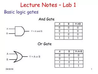
Experiment 2Basic Gates • Connect pins 6 (X) and 7 (Y) to Out1 and Out0. • Connect pins 12-15 to In4-In1. Print the truth table. Label each output column with the appropriate gate. • Connect pins 16-19 to In4-In1. Print the truth table. Label each output column with the appropriate gate. • Explain the fuse maps.