Download
1 / 20
290 likes | 985 Views
X-Ray Crystallography and It’s Applications. By Bernard Fendler and Brad Groveman. Introduction. Present basic concepts of protein structure Discuss why x-ray crystallography is used to determine protein structure Lead through x-ray diffraction experiments

E N D
X-Ray CrystallographyandIt’s Applications By Bernard Fendler and Brad Groveman
Introduction • Present basic concepts of protein structure • Discuss why x-ray crystallography is used to determine protein structure • Lead through x-ray diffraction experiments • And present how to utilize experimental information to design structural models of proteins
Introduction to Protein Structure: “The Crystallographer’s Problem” • What is the crystallographer’s problem?: Structural Determination! • Structure ~ Function • Amino acids are strung together on a carbon chain backbone. • As a result: • Can be described by the dihedral angles, called φ, ψ, and ω angles. • Ramachandran Plot • Note: the crystallographer is not in the business of determining molecular composition, but determining structural orientation of a protein.
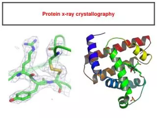
Introduction to:X-Ray Crystallography • x-rays are used to probe the protein structure: • Why are x-rays used? • λ ~ Å • Why are crystals used to do x-ray diffraction? • Crystals are used because it helps amplify the diffraction signal. • How do the x-rays probe the crystal? • x-rays interact with the electrons surrounding the molecule and “reflect”. The way they are reflected will be prescribed by the orientation of the electronic distribution. • What is really being measured? • Electron Density!!!
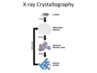
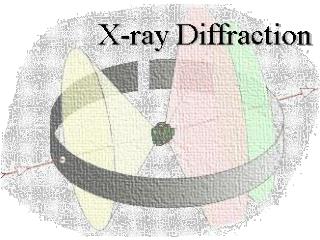
Performing X-Ray Crystallography Experimentsaka“Just Do It” • Bragg’s Law: • nλ =2dsin(θ) • Bragg's Law Applet • X-Ray Diffraction apparatus.
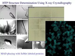
Performing X-Ray Diffraction • Resultant diffraction pattern from experimental setup • Diffraction pattern is actually a Fourier Transform of the electron distribution density.
Are We Finished? • No! • 1st: We still need to determine the atomic construction (all we have is electron distribution). • 2nd: There are problems with this analysis: • The phase problem • Resolution problems • Solved with Fitting and Refinement
Structural Basis for Partial Agonist Action at Ionotropic Glutamate Receptors • How do partial agonists produce submaximal macroscopic currents? • What is being investigated? • GluR2 ligand binding core. • Why is it being investigated? • Mechanism by which partial agonists produce submaximal responses remains to be determined. • What is going to be done? • 4 5-‘R’-willardiines will be used as partial agonists to determine the structure associated with the function. • Voltage clamping • X-ray crystallography • Outside out membrane patches for single channel analysis
Current Response • 1st experiment: • Dose Response Analysis using a two-electrode voltage clamp on an oocyte expressing the GluR2 receptor. • a.) and b.) show affinity of willardiines • Electronegativity is important • c.) and d.) show that: Size does Matter! • Note relative peak current amplitude with CTZ: • IGlu> IHW> IFW> IBrW> IIW • Note steady-state current amplitude without CTZ: • IIW > IBrW> IFW> IGlu> IHW • These data suggests that the efficacy of the XW to activate/desensitize the receptor is based on size.
Structure Meets Function • Mode of binding appears similar to glutamate • However, the uracil ring and the X produce a crucial structural change in the ligand-binding pocket.
Its all about domain closure. • Hypothesis: • the domains I and II need to be closer to produce an opening of ΔPro632 • This opening increases ion conductance.
Single Channel Analysis • They ask the question: • Do receptors populate the same set of subconductance states as with full agonists, but have different relative frequencies or open times? • To Answer the question, they first performed a fluctuation analysis of the macroscopic current by • slowly applying maximally effective concentrations of Glu, IW, and HW on outside-out membrane patches. • The weighted average conductance with Glu, HW, and IW are 13.1, 11.6, and 7.2 pS. • Suggests that the reduced efficacy reflects the activation of the open states with different average conductance.
Amplitude and Duration of Open States • To determine the amplitude and duration of the open states, a single channel analysis of the steady state responses was carried out. • Note in a and b, the distributions are the same (same conductane), so it must be that the open times of the pore for the different ligands are different.
Towards a Structural View of Gating in Potassium Channels • Ion Channel has 3 crucial elements: • Ion conduction pore • Ion gate • Voltage sensor • Architecture of Kv channels • Channel is a tetramer • N-terminus of S1 is thought to function as an intracellular blocker of the pore, which underlies fast inactivation—implies it is inside the membrane • S1-S2 linker glycosylated—outside of membrane. • S2-S3 cystein can be modified by MTS. • S3—protein toxins indicate that this is close to outside. • S4 N-terminus is accessible to MTS outside. • S4 & S4-S4 reacts to MTS inside. • S5-S6 is best defined because it remains well conserved across different channels.
Gate Structure • Pore domain is formed by S5 and S6 with S5-S6 lining the pore. • KcsA • x-ray structures support this model. • QA—pore blocker—gets stuck with rapid hyperpolarization—gate is on inside. • Further experiments indicate that the gate is on the inside. • MthK • Caught in an open state. • Pore Domains Structure and function • PVP motif (in many channels)—proline tends to kink helicies. • Increased MTS reactivity implies a larger opening with the PVP. • Metal interations not possible in the KcsA or MthK models.
Voltage Sensors: The Competing Models • S4 region is believed to be the sensor (charge rich region) • S2 & S3 have been shown to affect the voltage activation relationship. • Membrane Translocation Model • Protein charges move large distances through the membran. • Focused Field Model • Protein charges move smaller distances and focus electric field across membrane.
Model Verification!Or is it? • Note location of S4 • MT Model=yeah! • FF Model=awwh! • Some Problemos • Possible distortions in x-ray structure of KvAP • Open and closed structure mixed? • S1-S2 linkers suppose to be extracellular—from glycosylation sites experiments. • A number of other problems • Packing • MTS reactivity on both sides of membrane with approx. the same accessibility, active or not • Inconsistencies with orientations of other SX components in the structure. • Electron Microscopy shows a more expected conformation for the open position • Most noted discrepancy is that the N-terminus of S4 and S3 are probably much closer than what the x-ray structure shows.
Finally:Evidence for the Models • MTM: • Fab Fragments show biotin-avidin complexes on both sides of the membrane. Voltage sensor paddle (S3b-S4) • Red=external • Dark blue=internal • Yellow=both • FFM: • Fluorophore attatched to the N-terminal end of S4 maintains its wavelength • Energetically more favorable
Conclusion • Presented fundamentals of x-ray crystallography and how to interpret the data. • Presented a paper which discussed structure and function using x-ray crystallography with GluR2 receptors, and • Discussed another paper that reviewed the current accepted structures of Kv receptors and problems/inconsistencies with them.