Download
1 / 26
260 likes | 410 Views
NEES-CABER Group Meeting Work Progress at UMR. Meeting Date: 9/18/2007. UMR – Progress Overview. Experimental Work – Schedule & Deadline. - Published

E N D
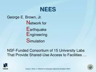
NEES-CABER Group MeetingWork Progress at UMR Meeting Date: 9/18/2007
- Published “Seismic performance of RC bridge columns subjected to combined loadings including torsion", May 16-19, 2007, ASCE Structures Congress 2007, Long Beach, California, USA . - Conferences (Abstracts Submitted) “Torsion-Flexure-Shear Interaction on the Behavior of Reinforced Concrete Members”, AGS’ 08, Second Euro Mediterranean Symposium On Advances in Geo-material and Structures -08, May 7-8, Tunisia. “Behavior of RC Circular Bridge Columns under Combined Cyclic Bending and Torsion” AGS’ 08, Second Euro Mediterranean Symposium On Advances in Geo-material and Structures -08, May 7-8, Tunisia. “Torsion-Flexure-Shear Interaction on the Behavior of Reinforced Concrete Members”, CBC’ 08, 2008 Concrete Bridge Conference, HPC – Safe, Affordable, and Efficient May 4-6, 2008, Hyatt Regency, St. Louis, Missouri. “An Experimental Study on Behavior of RC Bridge Columns under Combined Cyclic Bending and Torsion”, CBC’ 08, 2008 Concrete Bridge Conference, HPC – Safe, Affordable, and Efficient May 4-6, 2008, Hyatt Regency, St. Louis, Missouri. Journals (In preparation) “Behavior of RC Circular Bridge Columns under Combined Cyclic Bending and Torsion”, Manuscript is under preparation and will be submitted to ACI Structural Journal Publications:
Bending-Shear Shear-Torsion Bending Shear Torsion Interaction Surface– Problem Definitions - Target of this Research Project Test Points of this research project Tested To be Tested Combination of Bending-Shear-Torsion M-V-T Interaction Surface
TEST RESULTS– Combined Bending, Shear and Torsion - Hysteresis Curve Ultimate Torque Spiral Unlocking Side T/M(0) = 52.3 k T/M(0.1) = 50.4 k T/M(0.2) = 43.2 k T/M(0.4) = 39.8 k Spiral Locking Side T/M (0) = 53.3 k T/M(0.1) = 51.9 k T/M(0.2) = 48.8 k T/M(0.4) = 45.6 k The difference of ultimate strength between locking and unlocking sides becomes larger with increasing T/M ratio.
TEST RESULTS– Combined Bending, Shear and Torsion - Hysteresis Curve Ultimate Torque 0 Spiral Unlocking Side T/M((∞) = 187.2 k-ft T/M(0.4) = 150.4 k-ft T/M(0.2) = 99.1 k-ft T/M(0.1) = 64.8 k-ft Spiral Locking Side T/M(∞) = 212.0 k-ft T/M(0.4) = 169.8 k-ft T/M(0.2) = 114.8 k-ft T/M(0.1) = 63.8 k-ft The difference of ultimate strength between locking and unlocking sides becomes larger with increasing T/M ratio.
Test Results– Moment-Torsion Interaction Diagram-At Peak Torque * The numbers in the figure are Torsion to Moment Ratio
Test Results – Long Columns with 3# spirals 3000 T/M-0.4 T/M-0.2 2500 T/M-0.1 Long. Yield T/M-0 2000 T/M-0/0 Spiral Yield Torque (k-in) 1500 Peak Torque 1000 Peak Moment 500 0 0 2000 4000 6000 8000 Moment (k-in)
Test Results – Effect of Change in Transverse Steel Reinforcement Ratio Long Columns with #3 and #4 spirals Long. Yield Spiral Yield Peak Torque Peak Moment With Increasing spiral ratio, torsional and bending strength is improved and helps to limit the spalling zone
Analytical Models-Modification of RA-STM Improvement of RA-STM in Circular Section • Estimation of proper ‘Td’-Shear flow zone • : no warping effect , satisfying Navier’s principle • Considering tension stiffening effect • : continuous prediction before and after cracking • Apparent truss action at the cracking point • : estimation of cracking torque and twist • Including the Poisson’s Effect • : prediction after the peak point • ► To minimize other parameters like confinement effect or locking and unlocking effect, comparison is carried out with the results of column with hoop reinforcement tested under pure torsion RA-STM td
Analytical Models-Results of RA-STM Peak point
Analytical Models-Further Study • Adopt material laws derived from sectional analysis • Material laws considering softening and Poisson effect simultaneously • 2D material laws → 3D material laws (illogical), however, this attempt can provide a possibility to extend an 2-D analytical model to 3-D model • Considering Confinement and Spalling Effect to Analytical Model • Both of them are interdependent and strongly affected by one another • Can STM model be modified for accounting these effects?
Analytical Models-Critical Issues in Circular Section y x z x z td td 3 D Model (xyz plane) STM : 2 D Model (xy plane)
Analytical Models-Spalling and Confinement Effect Axial Load Torque Bending Confinement Effect Spalling Poisson’s Effect
Fiber Element Formulations- Shear Element y u1 (x,y) Y x u u3 u2 u1 Curvature i j Shear Strain Axial Displacement
Fiber Element Formulations- Model with Stirrups Stirrups Concrete Beam sys syc ex gxy ey g ex ey From Lateral Equilibrium:
Fiber Element Formulations- Inclusion of Shear Deformation Y X Z ui uj
Equivalent Uniaxial Stress:Rotating Crack Model P cracks s2 s1 s1 s2 Element in Cartesian Coordinate System Element in Principal Coordinate System Stress/Strain Model In Principal Directions
Fiber Element Formulations- Validation with Test Result UC San Diego Column R3- Monotonic 22, #6 bars #2 hoops @ 5” Length of the column = 96” 24” 16” Double curvature column
Fiber Element Formulations- Validation with Test Result UC San Diego Column R3 – Cyclic
Fiber Element Formulations- Validation with Test Result 2.5” Dia. 24” Dia. NEES UMR– Cyclic Longitudinal Reinforcement 12, #8 bars Transverse Reinforcement #3 bars 2.75” Spacing Length of the column 12’