Download
1 / 36
360 likes | 554 Views
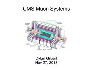
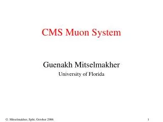
Operations and Performance of the CMS DT and RPC muon systems. G. Pugliese INFN & Politecnico of Bari On behalf of the CMS Collaboration. The CMS detector. Muon Spectrometer. Silicon pixel & strip tracker. Electromagnetic calorimeter (Scintillating PbWO4 crystals) . Hadron calorimeter

E N D
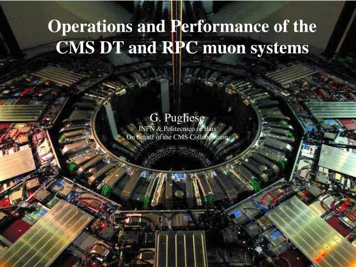
Operations and Performance of the CMS DT and RPC muonsystems G. Pugliese INFN & Politecnico of Bari On behalf of the CMS Collaboration
The CMS detector Muon Spectrometer Silicon pixel & strip tracker Electromagnetic calorimeter (Scintillating PbWO4 crystals) Hadron calorimeter Plastic scintillator/brass Weight: 12000 t Length: 21.6 m Diameter: 15 m Magnetic field: 3.8 T
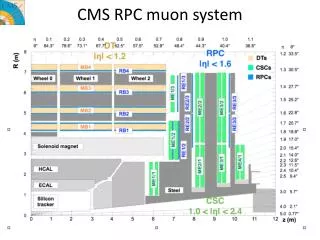
The muon spectrometer Robust, efficient and redundant muon system • Planar endcap region: • 4 planar stations interleaved with the iron return yoke plates (the 4th will be installed in 2013-14). • Cathode Strips Chambers and Resistive Plate Chambers • Requirement of m system: • identification of muons • measurement of their transverse momentum • bunch crossing (BX) assignment • Cylindrical barrel region: • 4 coaxial stations interleaved with the iron return yoke plates. The stations are grouped into5 wheelsaround the beam line • Drift Tube and Resistive Plate Chambers
Drift Tube Chambers DT chamber • covers 0 < |h| < 1.2 • 250 chambers • 3 Super Layer/chamber: 2 SL to measure the r – f coordinatesand 1 SL the r – z (except for MB4) • 4 layers/super layer • 42 mm x 13 mm cells for a total of 172000 • Gas mixture: Ar + CO2 (85 % -15%) DT Super Layer Spatial resolution per wire ≈ 250 mm Maximum drift time ~ 400 ns Almost linear space-time relationship ~ 55 μm/ns
Resistive Plate Chambers • covers 0 <|h | < 1.6 • 912 chambers (480 in barrel and 432 in endcap) • Double gaps gas chamber: 2 mm gas width • 110000 electronic channels and 3500 m2 of active area • Bakelite bulk resistivity: r = 2-5 x 1010 cm • Strip width: 2 ÷ 4 cm. • Gas mixture: C2H2F4 + isoC4H10 + SF6 (40% of H) • 95.2% 4.5% 0.3% • Operated in avalanche mode Spatial resolution ≈ 1 cm (depending on strip width) Timeresolution ≈ 2 ns
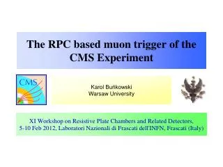
CMS trigger system L1 MuonTrigger Two level trigger system filters out “interesting” events: Level 1 trigger (made by custom electronic): 40 MHz 100 kHz latency < 3.2 ms High Level trigger (made by a processor farm): 300 Hz decision made in 1s Local trigger Segment RPC hits CSC hits DT hits Local trigger Segment Pattern Comparator L1 Calorimeter Trigger Track finder Track finder m m m Global Calorimeter Trigger Global Muon Trigger e/, J, ET, ETmiss m DT local trigger: provide trigger segments (in f and q view) for each chamber. Each trigger segment has to be associated to the BX at which the m candidate was produced. RPC trigger: the RPC hits are compared with predefined sets of patterns. A m candidate is produced if the hits fit a pattern and are in the same BX. Global Trigger L1 trigger 100kHz
CMS in operation 2010 2011 2012 CMS efficiency ≈ 92% CMS efficiency ≈ 91% CMS efficiency ≈ 92.5% Very high CMS efficiency in 2010 and 2011. Even better in 2012. % • Very low contribution of DT and RPC systems to the CMS downtime: less than 1.5 %.
CMS active channels • Fraction of active channels: • larger then 98% for RPC. Stable in time. • above 99 % for DT. Key of success: clear procedures for a prompt intervention during all beam-off and Technical Access time RPC and DT inactive channels are mainly caused by failure of the electronics located near or inside the chambers. Not accessibly since 2009. They will be recovered during long shutdown 2013 -14.
RPC working point calibration At the beginning of 2011 and 2012, an HV scan was done in order to study the chambers’ Working Point and to monitor in time the performance. The luminosity lost because of the RPC calibration was very low 3.3 pb-1 and 6.2 pb-1, in 2011 and 2012. HV distribution for all RPCs as measured at the 50 % of the efficiency Average efficiency vs HV for all RPCs. The different WP for Barrel and Endcap chambers depends on different construction techniques used.
RPC performance stability From July 2011 on, the WP is automatically corrected taking into account atmospheric pressure variations. The system is now running more stable. CMS 2011 Preliminary Without pressure correction With pressure correction CMS 2011 Preliminary Without pressure correction With pressure correction October 2011 April 2011 Barrel average efficiency history April 2011 October 2011 Barrel cluster size history
RPC efficiency 2D Efficiency map 3Defficiency view of one of the barrel wheels CMS 2011 Preliminary √s = 7 TeV Muon Radiography: the chamber efficiency can be studied in details, with a resolution of ≈ 1cm2. Spacers, border effects can be easily spotted. For few chambers, the stability in time of inefficient zones is under observation. No degradation observed up to now. CMS 2011 Preliminary √s = 7 TeV
DT Spatial resolution • Single hit resolution: • from the distribution of hit residuals with respect to the reconstructed segment. • r - f view: ≈ 200-350 mm • get better at large η due to longer trajectory of particles at large angles of incidence • worse in MB4 due to missing r-z super-layer • r – z view ≈ 250-750 mm • get worse at large η due to larger angle of incidence on crossing particles (deviations from linearity) r–f view r r W-2 W-1 W0 W+1 W+2 r–z view f h z
DT local reconstruction efficiency • Local reconstruction efficiency: • Tag (a global muon) & Probe (a tracker track) method applied to di-muons from Z° decays. • Efficiency for all chambers > 97% r f Segment reconstruction efficiency in all station 2 chambers in r – f view. Good agreement with Monte Carlo simulation. r-f view
DT Local trigger performace • DT local triggerefficiency: the presence of a trigger segment when there is a reconstructed track segment in the same chamber. • the drop in MB4 is due to two known problematic chambers. • System synchronization Average trigger efficiency: 93.5 % in 2011 and 93.7 % in 2012 Time distribution for DT: 98 % of highest quality DT trigger segments are in the correct BX.
RPC Trigger performance • RPC trigger efficiency: Tag &Probe method on di-muons from J/Y and Z resonances. Tag is a global muon which triggers the event. Probe is a tracker track (identified as a muon by the two-muon invariant-mass constraint). The efficiency is measured for the probe muon. CMS 2011 Preliminary √s = 7 TeV • System synchronization L1 RPC efficiency above 90% in the barrel region. probe with pT> 20 GeV/c from Z’s probe with pT< 20 GeV/c from J/ψ’s Time distribution for RPC: 99.89 % of RPC hits are in the correct BX.
DT Background study @ Inst. Luminosity ~ 1033 Hz/cm2 • Higher rate in: • external wheels W+2 and W-2. • outermost stations affected by slow neutron gas • Innermoststations affected by Hcal particle leakage • Top – bottom asymmetry due to wheels’ supports and steel flooring MB4 At luminosity of 1034cm-2s-1: max rate < 5 Hz /cm2 MB3 MB2 MB 1
RPC Background study CMS Preliminary 2011 • Background rate vs instantaneous luminosity • Barrel region: same background pattern as measured by DT. • Endcapregion: higher rate in external disks and inner rings (RE+2 and RE+3 R2) Barrel Endcap • No significant issues with increases of luminosity up to 1034cm-2s-1 : • max rate of 10 Hz/cm2(Barrel) • 20Hz/cm2 (Endcap) • Average rate ≈ 3 Hz/cm2 (Barrel) • ≈ 6 Hz/cm2(Endcap)
Conclusions • The CMS DT and RPC systems are operating extremely well delivering good triggers and data for physics: • the contribution to the CMS downtime is very low: less then 1.5 % • the fraction of active channels is very high and stable: more then 98%. • After 3 years of LHC running with increasing instantaneous luminosity and 6 years from the end of construction, the detector performance is within specifications both as triggering and as reconstruction system: • The RPC performance is stable with no degradation observed. Efficiency more then 95 %. • DT local reconstruction efficiency more then 97 %. • Excellent synchronization and efficiency of the trigger system. • Background measurements are within expectation. No significant issues for running at nominal luminosity.
The Large Hadron Collider Large Hadron Collider is a proton-proton collider, with centre of mass collision energies of up to 14 TeV. Installed 100 m underground in a tunnel 27 km long. Two high luminosity experiments, ATLAS and CMS, aiming at a peak luminosity of 1034cm−2s−1.
Triggering on di-muons in 2011 Impressive di-μ spectrum!!! Dimuon mass distribution obtained from overlapping several trigger paths. Dimuon triggers fundamental for searches but used also for calibrations
Muon Reconstruction Tracker track reconstruction Standalone Muon reconstruction Performed using DT/CSC segments & RPC hits Local reconstruction Performed within single chamber Global muonreconstruction (out side –in): a standalone muon is propagated to match a tracker track. If matching is positive a global fitting is performed. Tracker Muon (inside – outside):a tracker track is propagated to muon system and qualified as muon if matching with standalone or one segment.
RPC Barrel Station Forward Station • Barrel and Endcap chambers have different geometries and have been built in different sites with different construction techniques. • Gaps: in Italy for the Barrel and Korea for Endcap • Chambers: Bulgaria and Italy for Barrel and China, Pakistan and Cern for endcap.
RPC in the muon reconstruction Example of a track (in red, 1 DT segment + 2 RPC hits) that will fail in reconstruction if the RPC hits are removed in the track fitting tag-and-probe method using J/Ψ resonance Probes: Muons reconstructed with RPC hits Passing Probes: Muons reconstructed without RPC hits Passing probes Probes efficiency= RPC hit contribution is more evident for pT < 7 GeVand in the crack regions between adjacent wheels
3/4 RPC trigger algorithm: Pattern Comparator (PAC) The RPC hits are compared with the predefined set of patterns. Each pattern has assigned a transverse momentum (pT) and sign (depending on the track banding by the magnetic filed). Muon candidate is recognized if RPC hits fit to the pattern and are in the same 25 ns clock period (BX) A muon candidate is produced even though not all layers have hits. The minimum required number of fired layers is 3 (out of 3, 4, 5 or 6 layers available, depending on a detector region). In this way the trigger efficiency does not suffer from the limited geometrical acceptance and inefficiency of the chambers. The number of fired planes defines the candidate quality. The quality is used for the candidates sorting and “ghost busting” (cancellation of duplicated candidates). RPC layers strips A pattern is a set of AND gates connected to selected strips
RPC Trigger The efficiency of RPC PAC trigger for identifying muons is a convolution of: • εacceptance– geometrical acceptance of the RPC detector (fraction of muons crossing at least 3 chambers), • εchambers– chambers intrinsic efficiency, • εpatterns– patterns efficiency i.e. probability that the chamber hits of a “triggerable” muonfit to any pattern; “triggerable” muon– hits in at least 3 RPC layers inside the eta-phi cone covered by one PAC unit and in the same BX εtriggerablemuon=εacceptanceεchambers Endcap Barrel Endcap Good quality offline muons compatible with vertex, with pT > 10GeV/c, matching the RPC candidate. Minium-bias dataset.
Method to study the RPC performance Segment extrapolation method: a DT/CSC segment of high quality, associated to a stand-alone muontrack, is extrapolated to RPC strip plane. For each extrapolated impact point, the RPC efficiency is computed looking at RPC Hits in a range of +/- 2 strips from the extrapolated point
RPC spatial resolution Barrel: from σ = 0.81 cm in the inner, to σ = 1.32 cm in the outer station. Strip widths range from 2.28 cm to 4.10 cm Endcap: σ= 0.86 cm in the inner, to σ = 1.28 cm in the outer ring. Average strip widths range from 1.95 cm to 3.63 cm
Chamber performance: cluster size Cluster size distribution Cluster size .vs. HV Working Point CMS preliminary 2011 CMS preliminary 2011 Runs without WP pressure correction, Runs with WP pressure correction.
RPC noise Noise distribution for all barrel and encap chambers at WP operation. The average value is ~ 0.08 Hz/cm2
RPC Monitoring of the current Current is correlated to the beam intensity Current without beam is stable in time
Atmospheric Pressure monitoring HV working point is calculated taking into account the pressure variations HV_effective = HV ∙ Po/P ∙ T/To Po = 965 mbar, To = 293 K ~1% P variation = ~ 100 V difference
DT time resolution In addition to the measurement of the track position and direction, DT provides a measurement of the arrival time of the track to the chamber. The arrival time of a track in each DT chamber is reconstructed allowing a common displacement of the hits from the wire position to be a free parameter in the segment fit. Assuming Vdrift constant => common displacement ≡ shift in the time of the track The black distribution shows a clear tail due to the presence of δ-rays. The red distribution shows the local time for segments passing a χ2 quality cut. Measured local time distribution for all chambers for all stations.
DT plan for LS1 The DT Local Trigger is implemented using dedicated electronics located both on the chambers (minicrates)and on the balconies surrounding the detector, the Sector Collector (SC). Minicrate Replacement of theta TRB (Trigger boards): Minicratescontain TDCs and BTI (ASIC wirebond) whichareobsolete, no more ASICs can be produced, and sensitive to thermal stress during switch on/off. Current stock of spares is a potential issue. Plan: replace theta TRB (in MB1 and 2 in W+2/-2 ) with the new boards based on FPGA. Cannibalize BTIM from replaced boards to enlarge number of TRB φ and θspares. Relocation of Sector Collector from the cavern (UXC) to the counting room (USC): the flow of Minicrate data goes through the Sector Collectors (one per wheel) in the detector towers. This can constitute a potential single failure points, given the limited access to UXC. All Minicrateswill be connected to USC with optical fibers.
DT Trigger The DT Local Trigger is implemented using dedicated electronics located both on the chambers (minicrates)and on the balconies surrounding the detector, the Sector Collector (SC). BTIs: the signals coming from single wires are initially processed by Bunch and Track identifiers (BTIs) that operate rough track fitting within a single SL and perform BX assignment. TRACOs: the Track Correlators (TRACOs) is devoted to match the information coming from the two φ- SLs and improve the parameter measurements. TS: the Trigger Server (TS) performs a quality based selection on the segments coming from different TRACOs. SC:information from chambers of a single sector is forwarded, on the balconies surrounding the detector, to the Sector Collector (SC) that has to further refine the sorting, perform synchronization on data coming with different latencies, and send the signal to the DT Regional Trigger. The DT Regional Trigger performs correlation between the track segment received by the SC boards in order to build full muon tracks. Best track candidates are selected by the Muon Sorter and (up to) four candidates per BX are send to the Global Muon Trigger.