Download

1 / 28
320 likes | 556 Views
Low-cost bump bonding activities at CERN. Sami Vähänen, Timo Tick & Michael Campbell. Sami Vähänen – CERN TWEPP-10 Workshop 22 -September-2010. Outline. Introduction Under Bump Metal (UBM) deposition Electroless Nickel (EN) process introduction Test vehicle chip description

E N D
Low-cost bump bonding activities at CERN Sami Vähänen, Timo Tick & Michael Campbell Sami Vähänen – CERN TWEPP-10 Workshop 22-September-2010
Outline • Introduction • Under Bump Metal (UBM) deposition • Electroless Nickel (EN) process introduction • Test vehicle chip description • Flip chip tests and results • Solder ball placement technology and test on a Timepix chip • Summary Sami Vähänen – CERN TWEPP-10 Workshop 22-September-2010
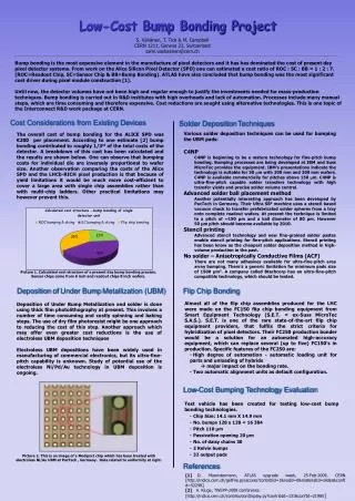
Low-Cost µ-Bump Bonding - Introduction • Bump bonding (BB) costs for a single pixel detector unit have been € 200 – € 300. • ReadOut Chip (ROC) : Sensor Chip (SC) : BB (cost ratio) = 1:2:7! • Increase in pixel detector area in the LHC upgrade – coverage of ten(s) of square meters? • BB is a major cost issues and a motivation for the low-cost study • Issue with low BB volumes at CERN • No constant need for BB technology • High price of BB services • Flip chip assembly part has caused the rise in total costs during last two years (pie diagrams) • Studied low-cost BB technologies have to exist still after 10 years and have to be compatible with 300 mm wafers. • Development has to be done on all fields of the pie diagrams for getting to ultimate low-cost BB solution. Sami Vähänen – CERN TWEPP-10 Workshop 22-September-2010
UBM Deposition • Electroplating has typically been used for solder bumping pixel of wafers. • Well characterized and reliable technology, but rather expensive in small-scale production. • Electroless Nickel (EN) under bump metallization (UBM) is studied as a corner stone for low-cost BB in this presentation because: • EN is suitable for various flip chip scenarios • EN can be processed without lithography • Batch processing - high-volume capability and affordable price • Reliable UBM – thick Ni as diffusion barrier for solder • Electroless technology could substitute traditional electroplating processes in certain bump size/pitch window in combination with complementary solder deposition techniques. • Solder ball placement solutions are also studied for low-cost solder deposition. • Anisotropic conductive films (ACF) could be used, but there aren’t many suitable films available for area array type fine-pitch applications (issues with small pad area). • This presentation focuses on the testing of EN UBM’s. Sami Vähänen – CERN TWEPP-10 Workshop 22-September-2010
Electroless Nickel (EN) Process Flow Source: Pac Tech publications, ref #62: http://www.pactech.com/index.php?option=com_content&view=article&id=154&Itemid=21 Sami Vähänen – CERN TWEPP-10 Workshop 22-September-2010
CERN Test Vehicle Wafers (1/2) • To use EN on real wafers, the process have to be tested and characterized. • Test vehicle layout was designed at CERN to serve the low-cost flip chip, TSV and large area tiling development work. • Typical interconnection densities for pixel detectors (55 µm & 110 µm pitch). • Test vehicle has daisy chains and Kelvin test structures to characterize the interconnection yields and resistances at three interfaces: • Flip chip bumps (21k/chip) • 32 daisy chains • 2 Kelvin bump test structures • TSV’s (196/chip) • 33 daisy chains • 5 Kelvin vias • BGA joints (100/chip) • 2 daisy chains • Layout is also suitable for chip-to-wafer and wafer-to-wafer bonding. • Wafers were processed at VTT by the authors. Picture of CERN Test Vehicle dummy readout chip Sami Vähänen – CERN TWEPP-10 Workshop 22-September-2010
CERN Test Vehicle Wafers (2/2) • Wafers (150 mm) were processed in two batches : • 1st batch of 24 wafers processed with AlSi(1%) wiring layer – typical for sensor wafers • Electroless Nickel – Electroless Palladium – Immersion Gold (ENEPIG) UBM process at Pac Tech • 2nd batch of 17 wafers processed with AlSi(2%)Cu(1%) wiring layer – very close to the topmost metal on readout wafers AlSi(1%)Cu(0.5%). • Electroless Nickel - Immersion Gold (ENIG) UBM process at Pac Tech • The purpose of two separate batches was to study the EN quality with and without having Cu alloyed in Al. • A third small batch of wafers was processed using the standard VTT electroplating process. Eutectic tin-lead solder bumps with Ni UBM were electroplated on the wafers. • Well known and reliable bumping technology • Most of the chips were bonded on electroless UBM pads • A small number of chips were used as a flip chip reference Sami Vähänen – CERN TWEPP-10 Workshop 22-September-2010
ENIG UBM on Test Vehicle Chips • SEM pictures of ENIG UBM pads on test vehicle chips are presented below. • UBM diameter ~ 27 µm, height 4 µm • Picture on the left, a single ENIG UBM pad. • Picture on the right taken with Angle-Selected Backscattered (AsB) mode. • Heavy elements (Ni UBM pads) are shown as brighter colours Sami Vähänen – CERN TWEPP-10 Workshop 22-September-2010
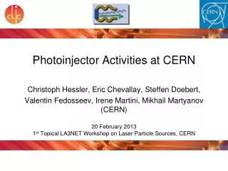
ENEPIG UBM Tests with Timepix Wafers • Test vehicle wafers were used for gathering statistics from FC assemblies. • Real CMOS wafers were processed with ENEPIG to see if the EN UBM process is feasible on real pixel wafers. • ENEPIG UBM was grown on Timepix wafers with two different pitches • 55 µm – without photoresist mask • 110 µm – with photoresist masking. Chips were electrically measured after EN process – no degradation in electrical performance. ENEPIG UBM pads on Timepix chip (110 µm pitch) ENEPIG UBM pads on Timepix chip (55 µm pitch) Sami Vähänen – CERN TWEPP-10 Workshop 22-September-2010
Flip Chip Tests and Results Silicon chip Al wire Electroplated Ni UBM SnPb Solder bump ENIG = electroless Ni/Au UBM Al wire & passivation Silicon chip Sami Vähänen – CERN TWEPP-10 Workshop 22-September-2010
Bump Structure & Assembly Procedure • Assemblies were built using three different flip chip structures • Reference structure: electroplated (asymmetric) solder bump structures used on both sides of chips to be mated (picture 1) • AlSi(1%)–ENEPIG structure: Electroplated solder bumps soldered on ENEPIG UBM (picture 2) • AlSi(2%)Cu(1%)–ENIG structure: Electroplated solder bumps soldered on ENIG UBM • Flip chip bonding was done with FC150 flip chip bonders, with tack bonding cycle. • Assemblies were picked up on a tray and run through a batch reflow process at 230 ˚C in reducing ambient. 2 1 Soldering on EN using ENEPIG and ENIG UBM pads Reference technology using VTT process Sami Vähänen – CERN TWEPP-10 Workshop 22-September-2010
Results from Daisy Chain Structures - Yield • Calculated yields based on functional daisy chains can be seen on table below: • Reference technology had 100 % yield. • AlSiCu-ENIG technology showed also very good yields which indicates that the technology is good enough to be used for pixel chips. • Notice the poor yield with AlSi-ENEPIG technology, especially if the average resistance per joint is limited to 1 Ω max (resistances from wiring weren’t eliminated) • Major contact resistance issue at AlSi – ENEPIG interface Sami Vähänen – CERN TWEPP-10 Workshop 22-September-2010
Results from Daisy Chain Structures • Resistances of complete daisy chains have been plotted in the graph below. • Huge differences in daisy chain resistances with AlSi(1%)-ENEPIG UBM technology (red bars) • Reference and AlSiCu-ENIG technologies have equivalent resistances Sami Vähänen – CERN TWEPP-10 Workshop 22-September-2010
Results from Kelvin Structures (1/2) • Kelvin bump structures revealed more detailed information about individual FC joint resistances. • Issue with the first batch of electroless UBM’s (AlSi-ENEPIG). Graph below. • Joint resistances varied in the range of several decades, which also explains the huge variation in the daisy chain resistances. • Reason behind the unstable joint resistance values was studied with the help of cross-sectional samples of the bump structures and inspecting them with SEM. Sami Vähänen – CERN TWEPP-10 Workshop 22-September-2010
Results from Kelvin Structures (2/2) • Joints made with reference and AlSiCu-ENIG technologies showed much smaller and more stabile joint resistances (average 19 mΩ) than done with AlSi-ENEPIG. • 4 µm thick electroless Ni causes a rise in the joint resistance for electroless deposited UBM’s. • Standard deviation of 7 mΩ is perfectly fine, but larger than with reference technology. Sami Vähänen – CERN TWEPP-10 Workshop 22-September-2010
SEM Imaging of Bump Structure(s) • Cracks were found at AlSi(1%) – ENEPIG interface (left picture). • Hundreds of bump structures were inspected and tens of cracks were found • The cracks would be a very logical reason behind the high daisy chain resistances and variation of resistances. • Cracks are critical if dealing with small passivation openings (20 µm in this case) AlSi-ENEPIG AlSiCu-ENIG Sami Vähänen – CERN TWEPP-10 Workshop 22-September-2010
SEM Imaging of Bump Structure(s) • No cracks were found at AlSi(2%)Cu(1%) - ENIG interface (right picture). • Note the difference in the roughness between Al – EN interfaces • AlSiCu-ENIG interface is much smoother • Better mechanical contact • Lower contact resistance • Having Cu in Al really improves the quality of Al-Ni interface! AlSi-ENEPIG AlSiCu-ENIG Zoom-in Zoom-in Crack at AlSi-Ni interface Seamless AlSiCu-Ni interface Sami Vähänen – CERN TWEPP-10 Workshop 22-September-2010
Solder Ball Placement Tests Sami Vähänen – CERN TWEPP-10 Workshop 22-September-2010
Solder Ball Placement– Standard Process • Solder ball placement technology is very interesting because: • Balls can be moved on wafers/chips individually or in a group (very cost-effective) • Solder volume is very precisely controlled • It is economically wise solution - investing only on the solder spheres, not the electroplating chemistry • Reworking possibility – high bumping yields • Solder balls are available in small sizes (40 µm) Classic solder ball jetting system using capillary force to place the solder spheres on UBM pads. Pac Tech
Solder Ball Placement – “Spitting” Process • The solder ‘spitting’ process uses a nozzle combined with a high-powered laser to instantly heat and to drop the molten solder balls in place one by one in sequence. • No mechanical contact to wafer • Relatively slow process (≈ 10 balls/s), but it may be appropriate for single chip (no complete wafers) prototyping in combination with EN UBM • Process has been used in industry for placing BGA-like bumps on wafers for moderate volume production. Technique has relatively low NRE costs • Yield enhancement by replacing missing bumps following group ball placement Advanced solder ball “spitting” system for placing individual solder spheres.
Solder Mass Transfer Process – “Gang Ball Placement” • The ultimate low-cost solder ball placement process is the mass transfer of solder spheres on the whole wafer at the same time. • Stencil grid with predefined holes and vacuum is used to lift the solder sphere. • Solder bumping defects can be repaired with the singe solder ball placement systems • Limited by ball size, minimum 60 µm at present therefore suitable for 100 mm pitch • Pac Tech foresees 40 µm bumps coming in 1-2 years. Solder mass transfer is very efficient process to attach the solder spheres to wafer
Solder Ball Placement Test • 40 µm sized solder balls (very advanced) were jetted (spitting process) on a Timepix chips with ENEPIG UBM with 110 µm pitch at Pac Tech. • Individual shear tests were done (30 bumps), giving an average shear force of 8 grams / bump (good results). • Looking forward to do more SBB tests on Timepix chips Sami Vähänen – CERN TWEPP-10 Workshop 22-September-2010
Summary Sami Vähänen – CERN TWEPP-10 Workshop 22-September-2010
Summary • Electroless Nickel (EN) UBM’s are studied because: • EN is a high volume capable & low cost technology, which is available in small volumes • EN makes various flip chip assembly scenarios possible • EN is a step towards the ultimate low-cost bump bonding process with small-scale wafer volumes Sami Vähänen – CERN TWEPP-10 Workshop 22-September-2010
Summary • Electroless Nickel (EN) UBM’s are studied because: • EN is a high volume capable & low cost technology, which is available for us • EN makes various flip chip assembly scenarios possible • EN is not a complete solution for solving the high price of BB, but it is a major step towards the right direction • Test vehicle chips were assembled with different bump structures and daisy chain and individual resistances were measured. • EN process worked well on AlSiCu metal – success! • Very similar results as with the reference technology • More development is needed with AlSi(1%) (sensor) metallization to overcome the cracking issues at Al-Ni interface. • However, the read out electronics is robust and could probably live with resistance variation Sami Vähänen – CERN TWEPP-10 Workshop 22-September-2010
Summary • Electroless Nickel (EN) UBM’s are studied because: • EN is a high volume capable & low cost technology, which is available in small volumes • EN makes various flip chip assembly scenarios possible • EN is a step towards the ultimate low-cost bump bonding process with small-scale wafer volumes • Test vehicle chips were assembled with different bump structures and daisy chain and individual resistances were measured. • EN process worked well on AlSiCu metal – success! • Very similar results as with the reference technology • More development is needed with AlSi(1%) (sensor) metallization to overcome the cracking issues at Al-Ni interface. • However, the read out electronics is robust and could probably live with resistance variation • For proof of concept ENEPIG UBM has been processed also on real CMOS wafers (Timepix). • More test to be done Sami Vähänen – CERN TWEPP-10 Workshop 22-September-2010
Summary • Electroless Nickel (EN) UBM’s are studied because: • EN is a high volume capable & low cost technology, which is available in small volumes • EN makes various flip chip assembly scenarios possible • EN is a step towards the ultimate low-cost bump bonding process with small-scale wafer volumes • Test vehicle chips were assembled with different bump structures and daisy chain and individual resistances were measured. • EN process worked well on AlSiCu metal – success! • Very similar results as with the reference technology • More development is needed with AlSi(1%) (sensor) metallization to overcome the cracking issues at Al-Ni interface. • However, the read out electronics is robust and could probably live with resistance variation • For proof of concept ENEPIG UBM has been processed also on real CMOS wafers (Timepix). • More test to be done • Solder ball placement process have been demonstrated with Timepix ROC’s with 110 µm pitch. Sami Vähänen – CERN TWEPP-10 Workshop 22-September-2010
THANK YOU FOR YOUR ATTENTION! Sami Vähänen – CERN TWEPP-10 Workshop 22-September-2010