Download
1 / 26
260 likes | 416 Views
LUSI Coherent X-ray Imaging Instrument WBS 1.3. Sébastien Boutet – CXI Instrument Scientist LUSI DOE Review August 19, 2008. Team Leader: Janos Hajdu Lead Engineer: Paul Montanez, P.E. Engineer: Jean-Charles Castagna Engineer: Armin Busse Designer: Richard Jackson. Outline. CXI Science

E N D
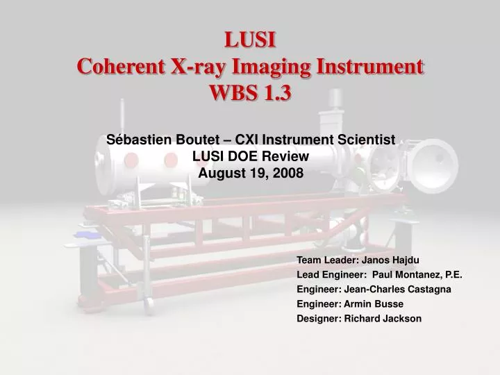
LUSICoherent X-ray Imaging InstrumentWBS 1.3 Sébastien Boutet – CXI Instrument Scientist LUSI DOE Review August 19, 2008 Team Leader: Janos Hajdu Lead Engineer: Paul Montanez, P.E. Engineer: Jean-Charles Castagna Engineer: Armin Busse Designer: Richard Jackson
Outline • CXI Science • CXI Location • System Physics Requirements • System Scope • System Description • System Layout • CD-4B Deliverables • Early Science • Schedule • Costs • Major Risks • 6-month Look-ahead • Summary
Science Team • Specifications and instrument concept developed with the science team. The CXI team leaders • Janos Hajdu, Photon Science-SLAC, Uppsala University (leader) • Henry Chapman, DESY, University of Hamburg • John Miao, UCLA
Coherent Diffractive Imaging of Biomolecules One pulse, one measurement Particle injection LCLS pulse Wavefront sensor or second detector Noisy diffraction pattern Combine 105-107 measurements into 3D dataset Gösta Huldt, Abraham Szöke, Janos Hajdu (J.Struct Biol, 2003 02-ERD-047)
Protein molecule injection LCLS detector detector To mass spectrometer X-ray diffraction pattern CXI Science • 3D bio imaging beyond the damage limit • Single injected reproducible biomolecules that can’t be crystallized • Proteins • Membrane Proteins • Viruses • Molecular complexes • Molecular machines • Biomolecular structure determination from nanocrystals • No need for large high quality crystals • 2D bio imaging beyond the damage limit • Live hydrated cells with particle injector • Nanoparticles • Quantum dots • Amorphous nanoparticles • High fluence X-ray-matter interactions • Damage studies during the pulse • Effect of tamper layers on damage
CXI Instrument Location Near Experimental Hall X-ray Transport Tunnel AMO (LCLS) XPP CXI Endstation XCS Source to Sample distance : ~ 440 m Far Experimental Hall
Far Experimental Hall Control Room Lab Area High Energy Density Instrument X-ray Correlation Spectroscopy Instrument Coherent X-ray Imaging Instrument
CXI Physics Requirements • Goals • Perform imaging of single particles at highest spatial resolution achievable using single LCLS pulses • Image biological nanoparticles beyond the classical damage limit using single LCLS pulses • Tailor and characterize X-ray beam parameters • Spatial Profile • Intensity • Repetition rate • Deliver the sample to the beam and control its environment • Key Performance Parameters • 4-20 keV energy range • Using the fundamental and third harmonic • 0.1-0.01% energy resolution • Particle Injector • 10-1000 nm size range
CXI Physics Requirements Photon Shutter Guard Slits Diagnostics Attenuators X-ray Transport Tunnel Pulse Picker Guard Slits Diagnostics Reference Laser Guard Slits Diagnostics KB Mirrors Guard Slits Diagnostics FEH Hutch 5 KB Mirrors Aperture Aperture Sample Environment Particle Injector Ion TOF-MS Detector Stage Wavefront Monitor Beam Dump
CXI System Description • 1.3.1 CXI System Integration and Design • 1.3.2 CXI X-ray optics • Focusing • 2 K-B systems • 1 micron focus • 0.1 micron focus • Coherence preserving and diffraction limited • Accept the full beam • 1.3.3 CXI Laser • Reference laser • Align the experiment without the LCLS beam • 1.3.4 Coherent Imaging Injector • Focused beam of particles of varying size • Particle size range: 10-1000 nm • Remotely controlled • Steering range : 10 mm • Reentrant range: 150 mm • Particle beam diagnostics • Beam position • Beam density
CXI System Description • 1.3.5 CXI Sample Environment • 1 micron Sample chamber • Vacuum better than 10 -7 torr • Sample translation stages • Aperture translation stages • Interfaces with Detector Stage. particle injector and ion TOF • Compatible with 1 micron KB system only • 1 micron instrument stand • Supports 1 micron Sample Chamber and Detector Stage • Sample diagnostics • Ion TOF mass spectrometer • Detector Stage • 50-2400 mm from sample • 0.1 micron Sample Chamber • Similar to 1 micron Sample Chamber • Compatible with 1 micron and 0.1 micron KB systems • 0.1 micron instrument stand • Supports 0.1 micron Sample Chamber, 0.1 micron KB System and Detector Stage 0.1 micron KB System
CXI System Description • 1.3.6 CXI Hutch facilities • Utilities • Cabinets • 1.3.7 CXI Vacuum system • 10-7 Torr • 1.3.8 CXI Installation
CXI Instrument Layout (X-ray Transport Tunnel) • Optics near the tunnel exit • Slits • Diagnostics • Pop-in Profile Monitors (Beam viewers) • Pop-in Intensity monitors • Intensity-Position Monitors (Non-destructive intensity monitors) • Attenuators • Pulse Picker • Reference Laser
CXI Instrument Layout (FEH Hutch #5) • 2 KB systems to produce 1000 and 100 nm focus • Each KB deflects the beam and the sample chamber must move with the beam • Precision Instrument Stand holds the Sample Chamber, the Detector Stage and the 0.1 micron KB system • 10 meters of space behind sample chamber • Wavefront Monitor to characterize the focus • Used as a second detector for low q data • Diagnostics • Slits
CXI Instrument Design 0.1 micron KB system Particle injector Diagnostics & Wavefront Monitor LCLS Beam 1 micron focus KB system (not shown) Sample Chamber with raster stage Detector Stage (Utilizing the LCLS Detector)
CD-4B components 1 micron KB System 1 micron Sample Chamber 1 micron Precision Instrument Stand Detector Stage Common optics and Diagnostics Pulse Picker Attenuators Some slits and diagnostics CD-4C components 0.1 micron KB System 0.1 micron Sample Chamber 0.1 micron Precision Instrument Stand Particle Injector Ion Time-of-Flight Common optics and Diagnostics Remaining slits and diagnostics CD-4B CXI Instrumentation
CD-4B CXI Science • Proof of principle imaging of test objects at diffraction limited resolution with a single LCLS shot. • 2D imaging of nanoparticles • Macromolecular structure determination from nanocrystals of proteins. • Proteins that form nanocrystals but do not form large crystals suitable for crystallography at synchrotron source. • 3D diffraction pattern built from multiple injected nanocrystals. • Relative orientation of each crystal determined from common lattice structure. • X-ray laser-matter interactions under high fluence • Measurement of damage during pulse and comparison to damage models. • Known samples on substrates • Known viruses • Calibrated nanoparticles • Damage versus fluence measurements. • Study of radiation damage mitigation techniques. • Thin tamper layers around a single molecule may slow the damage process. • Imaging of cells beyond the damage limit in 2D.
CXI Schedule Preliminary Design Reviews • Detector Stage – September 2008 • Reference Laser – October 2008 • 1 micron Sample Chamber – December 2008 • Particle Injector – August 2009 • 1 micron KB System – October 2009 • 1 micron Instrument Stand – December 2009 • Ion TOF – June 2010 Final Instrument Design Review – October 2009 Final Design Reviews • Reference Laser – December 2008 • Detector Stage – May 2009 • 1 micron Sample Chamber – June 2009 • Particle Injector – December 2009 • 1 micron KB System – March 2010 • 1 micron Instrument Stand – March 2010 • Ion TOF – July 2010 Project Ready for CD-3B - October 2009 Award PO • 1 micron KB System – April 2009 • 1 micron Sample Chamber – January 2010 • Detector Stage – January 2010 • 1 micron Precision Instrument Stand – May 2010 Receive • 1 micron Sample Chamber – April 2010 • Detector Stage – June 2010 • 1 micron KB System – August 2010 • 1 micron Precision Instrument Stand – September 2010 Project Ready for CD-4B - April 2011 FY08 FY09 FY11 FY10 All dates are early finish
CXI Major Risks • KB Mirror Systems • Vendor doesn’t meet specifications • Mitigation • Have SLAC quality control supervise the final fabrication process and final surface characterization • Identify vendors with proven capabilities • Delays impact other critical systems • Mitigation • Break the link between the KB0.1 mirrors and the chamber by building a second chamber to be used early with the KB1 system only • Sample Chamber • Lack of information regarding 0.1µm KB delays chamber engineering effort • Mitigation • Break the link between the KB0.1 mirrors and the chamber by building a second chamber to be used early with the KB1 system only • Particle Injector • Remote operation • Mitigation • Leverage institutional efforts to solve this problem • Move injector to a CD-4C deliverable to relieve schedule risk
6-month Look-ahead • 6 month “look-ahead” at Level 4/5 Milestones • ESDs released • CXI Detector Stage – Sept 08 • CXI Reference Laser – Sept 08 • CXI 1.0µm KB System – Sept 08 • CXI 1.0µm Precision Instrument Stand – Sept 08 • CXI 1.0µm Sample Chamber – Oct 08 • CXI 0.1µm KB System – Oct 08 • PRDs released • CXI Injector – Jan 09 • Preliminary Design Reviews • CXI Detector Stage – Sept 08 • CXI Reference Laser – Oct 08 • CXI Vacuum Equipment – Nov 08 • CXI 1.0µm Sample Chamber – Dec 08 • Final Design Reviews • CXI Reference Laser – Dec 08 • Vacuum System Equipment – Jan 09 • Cornell Detector Packaging (Participate in) – Feb 09 • Vendor Related • Release CXI KB Systems RFP – Jan 09 • Receive CXI KB Systems Vendor Proposals – Feb 09 • Far Experimental Hall Hutches • FEH H5 Preliminary Layout – Sept 08 • LCLS 30%, 60%, 90% hutch drawing review – Sept 08, Oct 08 and Jan 09 • LCLS FEH FDR – Jan 09
Summary • Instrument accommodates a wide variety of cutting edge research capabilities and fulfills the CD-0 mission • Instrument concept is based on proven developments made at FLASH and SR sources • Safety hazards have been identified in the Hazard Analysis Report (HAR) • Safety issues are considered at every step of the design and fabrication process • Scope of instrument fully defined • Resource loaded schedule developed through end of project • Preliminary design of key components is well advanced • CXI and LUSI are ready for CD-2 approval