Download
1 / 7
• 70 likes • 166 Views
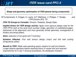
ITER issue card PFC-3. Shape and geometry optimisation of ITER plasma facing components W.Fundamenski, K. Krieger, A. Loarte, G.F. Matthews, V. Philipps, T. Tanabe, and ITPA Divertor-SOL TG. ITPA TG Groups to Consider: Divertor, Pedestal, Steady-State

E N D
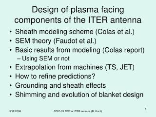
ITER issue card PFC-3 Shape and geometry optimisation of ITER plasma facing components W.Fundamenski, K. Krieger, A. Loarte, G.F. Matthews, V. Philipps, T. Tanabe, and ITPA Divertor-SOL TG ITPA TG Groups to Consider: Divertor, Pedestal, Steady-State Implied Action for ITER design activity: Apply more rigorous design rules for the ITER PFCs both at the local level (surface shape, geometry of castellations/gaps, tolerances of tile alignment) and more generally (limiter geometry, arrangement of limiters and dump-plates). Aims: reduction of hot spots and T-inventory Systems Affected: First wall armour design (main) and first wall cooling components (other) Benefit to ITER: Wider safe operating space margins for wall and divertor. Longer plasma operation before reaching tritium in-vessel limit and reduced requirements for in-situ T-removal procedures. No drawbacks foreseen.
Heat load reduction on leading edges Consider the design of the ITER-like wall for JET (similar issues as in ITER) Need for wide range of plasma configurations, high level of flexibility. Formation of hot spots at leading edges can limit lifetime of first wall. Excessive erosion at leading edges degrades the component life-time. Need to minimise leading edges in the design of PFCs eg. macrobrushes and castellations Flexibility might require additional, optimally shaped poloidal wall limiters separated by recessed wall areas. Schedule Implication: May delay schedule due to additional effort (design, R&D,procurement). This can be minimised if new R&D could be avoided, eg. heat flux tests. Cost Implication: significant. No estimate as yet.