Download
1 / 4
40 likes | 58 Views
Explore the distinguishing features of WP-CDMA technology, including high data rates, power control mechanisms, handover options, and control channel structures. Learn about collision detection, multi-code options, and removal of link maintenance channels.

E N D
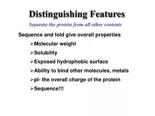
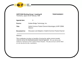
WP-CDMA Distinguishing Features 1. Uplink Common Packet Channel (All Rates) Common Packet Channel will transport all data rates up to · and including 2.048 Mbps. · Constant Power Level Preamble with 16 possible sequences Closed Loop Power Control, Preamble Ramp-up mechanism · Fast L1 ACK mechanism (within 250 micro-seconds) · • Collision Detection with Low Feedback Delay (2 ms) • Downlink Common Power Control Structure 2. Common Control Channel in the Downlink 3. Intra-frequency Hard Handover 4. Quick Handover 5. Structure of the WP-CDMA CCPCH (Common Control Physical Channel) • TM Common Pilot for coherent demodulation • Adjustable Power SCH1 And SCH2 for faster initial cell search 6. Multi-code Option for Higher Rates • The relationship between the VSF and number of multi-codes is the subject of • further study 7. Higher APC Rates 8. Removal of Link Maintenance Channel
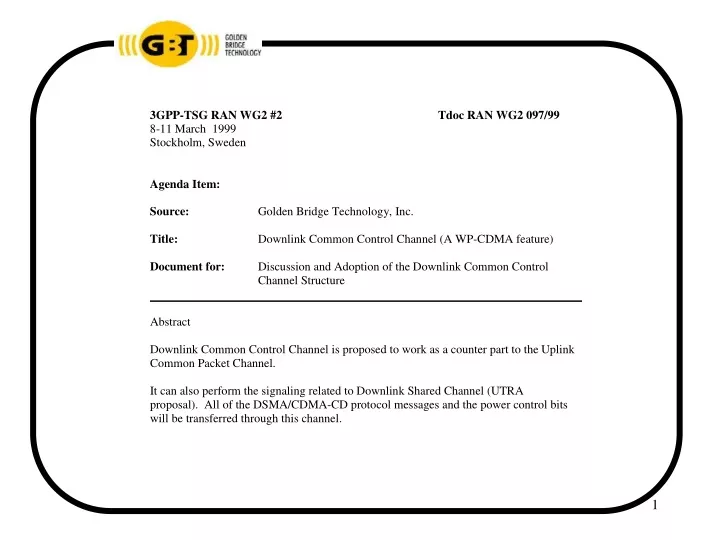
WP-CDMA Distinguishing Features DL Common Control Channel • There are N power control channels associated with each user. These power • control channels are time multiplexed. • The pilot symbols required for coherent detection are time multiplexed with the • other control information in the Common Control Channel in the DL direction. • Messages such as L1 ACK (Busy). Free. CD. ARQ ACK/NAK will be sent through • the Common control Channel as well. Some of the messages such as L1 ACK, • TPC and CD bits are not interleaved since fast response time is required. • L1 ACK requires a predetermined time allocation in the .625 ms slot. This is • required every other slot at the end of the DSMA/CDMA-CD mini-slot which • corresponds to the .25 ms guard time. • Other less delay sensitive messages and commands go through the signaling • channel which is time multiplexed with other information in the Common Control • Channel.
DL Common Control Slot Structure Pilots NPilots Slot 0 CD CD PC2 PC1 CD CD PCn SIGNALING … TFI SF=64 SF=TBD SF=TBD 625 µs L1 ACK NACK Pilots NPilots PC2 PC1 SIG SIG SIG PCn … Slot 1 TFI 375 µs