Download
1 / 15
150 likes | 303 Views
VHDL Statement Rules. Sequential areas Process Function Procedure Concurrent areas Architecture Block Generate. Sequential statements Signal assignment Variable assignment If/Then/Else Case Loop Next Exit Wait Return Function/Procedure call Assert Report Null.

E N D
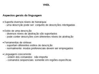
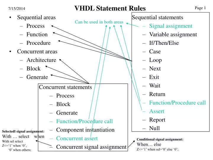
VHDL Statement Rules • Sequential areas • Process • Function • Procedure • Concurrent areas • Architecture • Block • Generate • Sequential statements • Signal assignment • Variable assignment • If/Then/Else • Case • Loop • Next • Exit • Wait • Return • Function/Procedure call • Assert • Report • Null Can be used in both areas • Concurrent statements • Process • Block • Generate • Function/Procedure call • Component instantiation • Concurrent assert • Concurrent signal assignment Selectedl signal assignment: With … select when With sel select Z<=‘1’ when ‘0’, ‘0’ when others; Conditional signal assignment: When… else Z<=‘1’ when sel=‘0’ else ‘0’;
VHDL Process The process concept comes from software and can be compared to a sequential program. If there are several processes in an architecture, they are executed concurrently. The syntax for the process: [<process_name>:] process [(<sensitivity_list>)] [is] begin <process_statement_part> end process [<process_name>]; VHDL-1993 (Sequential area) • There are Two types of process in VHDL: • Combinational Process • Clocked Process
Process Construct for Synthesis A process represents a group of logic elements (gates and/or flip-flops) with signal inputs and signal outputs. process Combinational process sensitivity list process(A, B, C) variable D: Std_Logic; begin if A='1' then D := B; else D := B or C; end if; F <= D; end process; Variable declare area A B F C Inputs will appear in conditions or in right-hand side expressions and may be in the sensitivity list. Outputs will be the target of signal assignments. (Internal declarations cannot be outputs).
Process Construct as Conditional CSA process(Sel, Data) begin if Sel="00" then Y <= Data(0); elsif Sel="01" Y <= Data(1); elsif Sel="10" Y <= Data(2); else Y <= Data(3); end if; end process; Combinational process Sel Y Data A process may have the same meaning as a CSA or a concurrent procedure call. Y <=Data(0) when Sel="00" else Data(1) when Sel="01" else Data(2) when Sel="10" else Data(3); Preferred because shorter and no sensitivity list to deal with.
Process Construct as Selected CSA process(Sel, Data) begin case Sel is when "00" => Y <= Data(0); when "01" => Y <= Data(1); when "10" => Y <= Data(2); when others => Y <= Data(3); end case; end process; Combinational process Sel Y Data A process may have the same meaning as a CSA or a concurrent procedure call. with Sel select Y <= Data(0) when "00", Data(1) when "01", Data(2) when "10", Data(3) when others; Preferred because shorter and no sensitivity list to deal with.
D D Q Q C D D Q Q E Latch Clk En if En = '1' then Q <= D; endif; process(Clk) begin if Clk'event and Clk = '1' then Q <= D; end if; Storage Elements Clocked process Combinational process Note: The "if" construct cannot be placed in a concurrent area. Flip-flop rising_edge(Clk)
D D Q Q C Clk Flip-flops/Registers Clocked process Flip-flops and registers must be represented as processes process(Clk) begin if rising_edge(Clk) then Q <= D; end if; end process; This D flip-flop has no initialization.
Schematic/VHDL Representations(storage/sequential/clocked) D D Q Q Clk C R Rst Active low Asynchronous reset/ Synchronous reset process(Rst, Clk) begin if Rst = '0' then Q <= '0'; elsif rising_edge(Clk) then Q <= D; end if; end process;
D(7) Q(7) D(6) Q(6) Q(5) D(5) D(4) Q(4) Q(3) D(3) D(2) Q(2) D(1) Q(1) D(0) Q(0) Clk Register (Eight-bit) D (7 downto 0) Q(7 downto 0) Clk process(Clk) begin if rising_edge(Clk) then Q <= D; end if; end process; This register has no initialization.
Ser_In Q(7 downto 0) Clk Shift Register (Eight-bit) concatenation process(Clk) begin if rising_edge(Clk) then Q <= Q(6 downto 0) & Ser_In; end if; end process; This register has no initialization.
Parallel-In/Serial-Out Shift Register (Eight-bit) signal D:Std_Logic_Vector(7 downto 0); D Ser_Out Ser_Out <= Q(7); process(Clk) begin if rising_edge(Clk) then if Load = '0' then Q <= D; else Q <= Q(6 downto 0) & '0'; end if; end if; end process; Load Clk concatenation
Binary Counter (Eight-bit) Q(7 downto 0) Count Clk Q(7 downto 0) + "00000001" Count process(Clk) begin if rising_edge(Clk) then if Count = '1' then Q <= Q + 1; end if; end if; end process; Clk Note: The VHDL shown must have a function "+" defined to be complete. This register has no initialization.
A B C D Clk Q 0 ns 10 ns 20 ns 30 ns 40 ns 50 ns 60 ns C A D D Q Q_r B C Clk CSAs with Processes (one flip-flop) C <= A and B after 5 ns; D <= not C after 10 ns; process(Clk) begin if rising_edge(Clk) then Q_r <= D; end if; end process;
A B A_r B_r C D Clk Q 0 ns 10 ns 20 ns 30 ns 40 ns 50 ns 60 ns A A_r C D Q D D Q Q D Q_r B C C C B_r Clk CSAs with Processes (multiple flip-flops) C <= A_r and B_r after 5 ns; D <= not C after 10 ns; process(Clk) begin if rising_edge(Clk) then Q_r <= D; A_r <= A; B_r <= B; end if; end process;
VHDL Process State Waiting (executed all statements of the process or “wait on” statement) (any of signals state in the sensitivity list or wait on is changed ) Executing