Download
1 / 20
200 likes | 230 Views
Thesis on fine pitch FPC for PHENIX Si Pixel detector development steps, crosstalk and impedance measurements, development motivation, and new TPC pad development. Detailed simulation and evaluation techniques presented.

E N D
TPC pad simulation for wide dynamic range application RD51 meeting at Kobe 2011 Sep 2nd Thesis: Fine pitch FPC(30m/30m L/S) for PHENIX Si Pixel detector H Tokyo Metropolitan Industrial Technology Research Institute Electronics Group Kohei Fujiwara, Takeshi Kobayashi fujiwara.kohei@iri-tokyo.jp Atsushi Taketani, Takaaki Isobe, RIKEN
Outline • Development motivation from Nuclear Physics • Development steps of a TPC pad • Crosstalk measurement • Impedance measurement • New TPC pad development • Summary
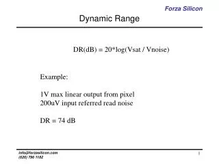
2. Development motivation • Heavy Ion 400MeV/A , measuring interaction products by TPC. • Pulse height induced in a detector ∝ Z2 • Target range of Z is Z~10. • MIP should be detected near by Z=10 • Dynamic range > 100 • In order to obtain the detection dynamic range, the crosstalk level should be less than 0.5%.
3. Development steps of a TPC pad We are developing a new TPC pad with RIKEN. 1. Electromagnetic simulation • Design lower crosstalk transmission line and pattern. • Layer structure, physical parameters • Current distribution, S-parameter calculation 2. Circuit Simulation for crosstalk Calculate crosstalk level in an adjacent line -> Required crosstalk level is less than 0.5%. 3. Making Test board for crosstalk evaluation 4. Design TPC pad
Development Software for the simulation Development of: Agilent Technology: Advanced Design System (ADS) • RF circuit, High Speed RF circuit • Monorisic Microwave IC (MMIC), RFIC • Transmission Line, Antenna Example of MMIC design
Electromagnetic simulation models Simulation Models Model1 w s Signal Signal h GND Model2 GND Signal Signal GND Model3 GND Signal Signal GND First, development of low crosstalk transmission line in TPC pad • 3 types of transmission line • Line width (w): 0.1 mm • Space (s): 0.1 mm • Line length: 36 mm • Thickness (h): 43 mm • Substrate: FR-4 (er=4.2, tan=0.015) • Conductivity: 5.8 x10⁸ S/m
Result of electromagnetic simulation Electromagnetic simulation model Current distribution Momentum Method Reflection Impedance 2.5 GHz 2.5 GHz Transmission 2.5 GHz Calculating the S-parameters from 10 MHz to 2.5 GHz. Model3 has the best characteristics.
Calculation model for crosstalk evaluation SMA connector model is included to make a realistic model. Without connector model is also prepared. SMA Model SMA Model Test board Transmitted line 50ohm Pulser 50ohm 50ohm 50ohm Crosstalk side Pulse width:50 nsec Rise time:10 nsec Fall time:10 nsec Pulse height:1 V
Crosstalk level in each models Model1 w s Signal Signal h GND Model2 GND Signal Signal GND Model3 GND Signal Signal Separator (GND) GND Crosstalk level: Induced pulse height / Injected pulse height Crosstalk level of Model3 is also the best in the measurement.
Test boards • To evaluate transmission line in Model2 and Model3. • Measured cross talk level, impedance are compared with simulation result. Model3 Model2 Transmission line Transmission line SMA Connector Line width (w): 0.1 mm Space (s): 0.1 mm
4. Crosstalk level measurement • Crosstalk measurement setup • 3 GHz analog bandwidth oscilloscope • Pulse Generator (Pulse height=4 V) Pulse Height of 4 V is set to obtain dynamic range. Input termination
Crosstalk level measurement result Red: Model2 Blue: Model3 Crosstalk level in Model3 is improved than the simulation. → It might be reason of SMA connector frequency characteristics.
5. Impedance measurement • Time Domain Reflectometry (TDR) • Agilent 86100C • TDR Module 54754A x 2 • Minimum pulse rise time:10 ps • To evaluate characteristic impedance in time domain. • Transmission lines • Finding failure point • Lines • Wire-bonding…
Impedance measurement setup Reflected pulse 35 ps Injection step pulse Composing Injection + Reflection pulse TDR (B.W=18 GHz) Test Board Oscilloscope + Pulser Open ended
Impedance measurement result 1 Test board Red: Simulated Blue: Measured 50 0.5 ns ~ 3.6 mm Test board of Model3 has better impedance characteristics. • Z ~ 55 • Line length by TDR measurement: ~ 36 mm • It is consistent with the real length.
Impedance measurement result 2 Red: Simulated Blue: Measured Red: Simulated Blue: Measured Model2 Model3 GND GND Signal Signal Signal Signal Separator (GND) GND GND It seems Model3 has better impedance characteristics. • Line impedance of transmission region in Model3 is flat than Model2. • Good result by separator (GND line) in Model3 → Electric force line can be shielded. Fluctuated Flat
6. New TPC pad Cross Section Layer1:Pad Via Layer2:GND Layer3:Signal Via Layer4:GND Layer5: Connector 5 Layers structure • 1 Pad area: 11 mm x 7 mm 5. New TPC Pad Comparison of New design and Model3 Design new TPC pad using Model3 5 Layer structure 1 Pad area: 11 mm x 7 mm Crosstalk evaluation New TPC Pad is improved -98.6% than Model3.
Simulation with Pad -98.6% than Model3.
7. Summary • We are developing lower crosstalk TPC pad including transmission line. • Crosstalk level by simulation: 0.08% • Crosstalk level by measurement: 0.04% • Requirement: <0.5%, it is satisfied. • Line impedance stability is confirmed by TDR. • Model3 has has good stability. • Starting new TPC pad simulation and design. • 1 Pad area: 11 mm x 7 mm. • 5 Layers structure • Do simulation including TPC capacitance (~10 pF) including transmission line. Seems fine.
Future Plan • Building with MICROMEGAS • Look at cross talk at readout electronics • Need wide dynamic preamp and ADC