Download
1 / 14
150 likes | 219 Views
Learn about culverts, structures carrying waterways under roads, with details on hydraulic design and example designs.

E N D
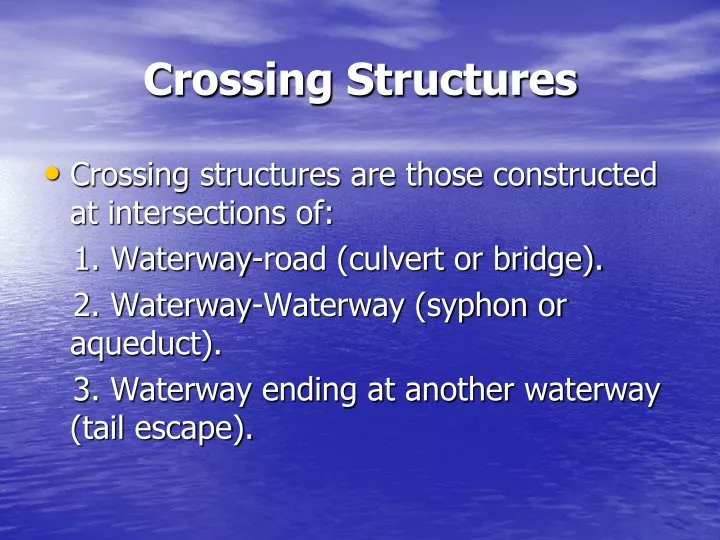
Crossing Structures • Crossing structures are those constructed at intersections of: 1. Waterway-road (culvert or bridge). 2. Waterway-Waterway (syphon or aqueduct). 3. Waterway ending at another waterway (tail escape).
Waterway Waterway Road Waterway Waterway Waterway Culvert or Bridge Syphon or Aqueduct Tail escape
The culvert is a closed conduit (pipe or box section) constructed to carry the discharge of a waterway under a road. The selection of the type of the culvert is based on the discharge as follows: • For Q ≤ 3.0 m3/sec use Pipe culvert. • For Q ≤ 12.0 m3/sec use Box section.
D S ≤ .15 m H ≥ .3 m d
Hydraulic Design The purpose of the hydraulic design is to select the culvert’s dimensions. The dimensions are selected based on: • Velocity through culvert between 1.0 to 2.0 m/sec. • Head losses is less then 15 cm. • Entrance submergence is at least 30 cm.
The only equation available is the continuity equation: Q = A . V Where Q is the discharge in m3/sec, A is the culvert’s cross section area in m2, and V is the water velocity through the culvert in m/sec. Since the discharge is known, the velocity must be assumed to determine the dimensions of the culvert. The velocity is usually assumed between 1.0 and 2.0 m/sec for practical reasons.
Once the dimensions are determined, then head losses must be checked. Head losses are calculated as follows, Where Hl is the head losses in m V is the velocity in m/sec g is the acceleration of gravity
Ce is the entrance coefficient of loss (= 0.5 ) Cf is the friction coefficient Co is the outlet coefficient of losses ( = 1.0 ) Friction coefficient can be calculated as follows,
Where f is coefficient depends on the culvert material and dimension, L is the length of the culvert and m is the hydraulic radius. The coefficient a and b are constant and depends on the material of the conduit. For Steel: a = 0.0048, b = 0.0256 For Concrete: a = 0.00316, b= 0.0305
Example 1: Design a culvert under a road. The discharge is 3 m3/sec and the water depth is 1.8 m. The culvert length is 20 m. • Sol. Q = 3 m3/sec * use pipe culvert assume V=1.3 m/sec A = Q/V = 2.31 m2 A = ∏ D2/4 * D = 1.7 m However, D ≤ 1.8 – 0.3 … 1.5 m
Then use 2 pipes …one pipe A = 1.155 m2 D = 1.3 m …. V = 1.13 m/sec … OK Check of heading up m = D/4 = 0.325 m f = 0.0052 Cf = 0.32 Hu = (1.13)2/(2*9.81) *(0.5+0.32+1) = 0.12 m … OK
Example 2: design a culvert under a road. The discharge is 5 m3/sec and the water depth is 2.2 m. The culvert length is 20 m. • Sol. Q = 5 m3/sec … Use Box culvert Assume V = 1.3 m/sec A = Q/V = 3.85 m2 H = 2.2 – 0.3 = 1.9 m S = 3.85/1.9 = 2.0 m
S < 1.5 H … OK V = 5/(1.9*2) = 1.32 m/sec Check for Heading Up m = 2*1.9/(2+1.9)*2= 0.49 m f = 0.00336 Cf = 0.14 Hu = 0.145 m … OK