Download
1 / 19
190 likes | 196 Views
FSSR Status Report: Completion of the Functional Design Phase. Jim Hoff , Abder Mekkaoui, Ray Yarema Particle Physics Division/Electrical Engineering Department. What is the FSSR?. The FSSR is BTeV’s full-custom silicon strip readout IC. FSSR stands for “Fermilab Silicon Strip Readout”.

E N D
FSSR Status Report:Completion of the Functional Design Phase Jim Hoff, Abder Mekkaoui, Ray Yarema Particle Physics Division/Electrical Engineering Department
What is the FSSR? • The FSSR is BTeV’s full-custom silicon strip readout IC. FSSR stands for “Fermilab Silicon Strip Readout”. • The analog front end is being designed in cooperation with INFN in Italy • The digital back end design as well as the full-custom chip layout will be performed here at Fermilab. • Among the most desirable design goals for the back end: The communication protocol between the DAQ system and the FSSR chip should be as close as possible to the FPIX protocol. • The more of FPIX that we can re-use, the fewer prototypes we will need, the lower the overall cost will be, and the faster the design will be realized.
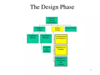
What is the functional design phase? • Prior to layout, we want a complete, accurate Verilog model of the FSSR. • The FSSR model must be structural and NOTbehavioral. In other words, it must consist of designable sub-blocks. • The FSSR inputs and outputs (with the exception of power and bias) must be finalized. • Finally, it must be tested with realistic data created by Monte Carlo analysis of the interaction region.
Functional Design (cont.) • At the end of the functional design process we have: • A thorough understanding of the algorithms necessary to accomplish the task at hand. • A design guaranteed to handle those algorithms • Feedback from the physicists as to whether or not we handle those algorithms well enough • A fair idea of the electrical problems that lay ahead • A rough floor plan of the layout • A Verilog model that can be used by others if they wish to do so I am here to report that this process has been completed for the FSSR. I am also here to explain the model to you, and to get any additional feedback from the collaboration.
FSSR Model Data Outputs Strip Inputs Control Inputs The Verilog Model
FSSR Model • Several architectures have been tested • The chosen architecture is called pseudo-Pixel. It is essentially identical to the FPIX architecture. • The 128 strips serviced by one chip are sub-divided into 16 sets of 8 strips. Each set is made to behave like a single column in the FPIX architecture. • FPIX is a 22x128 array of pixels. • FSSR will look like a 16x8 FPIX • The same programming interface and data interface used in FPIX can be used again in the FSSR. • This implies that there will be a 24 bit data word output by the FSSR. 4 bits will be necessary to encode the strip number; 5 bits will be used to encode the set number; 8 bits will be used for the BCO number and 1 bit will be used for the sync bit. This leaves 5 extra bits.
FSSR Model (cont.) • Both the FSSR Chip and this Verilog Model have the following inputs and outputs • 128 strip inputs • 1 BCO clock input • 2 Master Clock inputs • 1 each Shift In, Shift Out, and Shift Control • 6 140 MBPS data output lines • 1 output clock line • Both the FSSR Chip and this Verilog Model must be programmed (i.e. Send Data activated, Reject Hits deactivated, etc), and then strip data must be applied to its inputs.
128 “Strips” Ordered by BCO 128 “Strips” With timing info 1,2,4, or 6 serial lines + Output Clk SiliconStrip Det. Model FSSR Model DAQModel MonteCarloData FromPenneyKasper Data Outputs Report Strip Inputs Control Inputs BCO Clk, Master Clocks, Serial In, Out and Ctrl List Of Originals RecordedEvents, Misses, Matches The Verilog Model
Models the combination of the pre-amp rise time and the discriminator firing delay Models the combination of the pre-amp fall time and the discriminator firing delay Monte Carlo Data is has no timing information. It just answers the question: Was this strip hit this BCO? Silicon Strip Detector Model
DAQ Model • The DAQ model recognizes sync/status words and establishes an appropriate sync with the FSSR regardless of the number of active lines. • It reconstructs hit data from the serial output lines • It records all hit data in the “Recorded Data” file. • Finally, it records any unknown output words (i.e. binary X states) in the “Scratch Data” file. Ideally this should always be an empty file.
The Report • Line 1: Sum total of “Original Data” • Line 2: Sum total of “Recorded Data” • Line 3: Garbage Output • Line 4: The matches • Line 5: The missing “Original Data” • Line 2 + Line 5 should equal Line 1 • Line 6: Unmatched “Recorded Data” • Line 4 + Line 6 should equal Line 2 Efficiency = Line 4 / Line 1
Simulations Performed • All simulations assume 132ns beam crossing period • Front-ends were modeled as: • Slow: 60ns turn-on time/500ns dead-time • Fast: 10ns turn-on time/10ns dead time • 200ns: 20ns turn-on time/180ns dead time • Back-ends were modeled with • FSSR Clock = BCO Clock • FSSR Clock = 4x BCO Clock
Conclusions • The pseudoPix architecture is a 100% reuse of the FPIX architecture • The plan is to use the pseudoPix architecture with an eye towards running it with a back end clock equal to 4 times the BCO clock frequency. • Simulations indicate this will be no problem. Rigorous experiments with FPIX confirm that a 4x BCO multiplication is achievable. • FPIX acts as a prototype for the FSSR back-end. It is a proven design. Only layout will be required.