Download
1 / 8
80 likes | 103 Views
Learn about the unique features and differences of the prototype cryomodule compared to a standard linac module. Details include cryo-feed can specifications, end cap configurations, cooling systems, beamline transitions, and wire position monitoring. Presented by experts in the field.

E N D
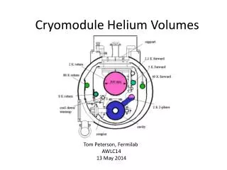
Cryomodule prototype Yun He, Dan Sabol, Joe Conway On behalf of Matthias Liepe, Eric Smith, James Sears, Peter Quigley, Tim O’Connell, Ralf Eichhorn, Georg Hoffstaetter
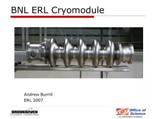
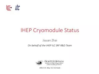
Differences of Prototype Module from Linac Module Prototype cryomodule Cryo-feed can End cap Flange-to-flange: 10.4 m Yun HE, MLC External Review
Cryo-feed can Cryo feed head from heat exchanger, to feed cryogen to module Two lines to be blanked off HGRP and six lines – 1.8K -- 5K (supply, return) -- 40-80K (delivery, supply, return) • Shield end section mounted to main shield • End plates in two halves Yun HE, MLC External Review
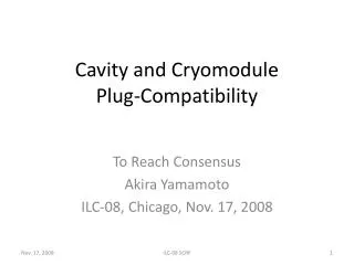
Cooling pipes Flanges/elbows to connect to cryo-feed head are pre-welded Yun HE, MLC External Review
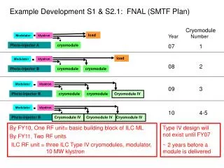
End cap • Piping blanked off • HGRP • 5K (supply & return) • 1.8 K • 40 K return • 40K delivery & supply lines connected by ½” tubing Port for access to tuner/GV Manual gate valve to be supported with G10 to HGRP, w/ key alignment • 40K shield curved inwards • Manual gate valve intercepted @80K Yun HE, MLC External Review
Cooling of 2nd half of HGRP for prototype module • For prototype, a second connection between HGRP and 2K-2 phase at far end provides cooling of the second half section of HGRP • A bellows section at very end on 2K-2 phase • This applies to the last cryomodule in the linac string Pipe support Yun HE, MLC External Review
Beamline warm-cold transitions • Warm-cold transitions, wall 1.65mm • Will have sliding joints on beamline outside module to accommodate beamline shifts at cold Gate valves intercepted @80K Replacement of SC magnets • Bellows section connects beampipe to end flange of can • allows for displacements of beamline at cold • Vertical: 1.2 mm • Longitudinal: 8 mm Yun HE, MLC External Review
Wire position monitor • For prototype module only, to monitor relative displacement between the wire and cold mass • Mounted on end cap flanges (room temperature), thus the wire position is not influenced by cool-down Heat treated CuBe wire (ɸ0.5 mm) is stretched parallel to the beam axis providing a position reference • Sensors attached to end flange of cavity LHe vessel • Two sensors for 1st, 3rd, 5th cavities to monitor pitch displacements • One sensor for each of the rest three cavities A WPM sensor consists of four striplines spaced 90° apart Yun HE, MLC External Review