Download
1 / 19
190 likes | 298 Views
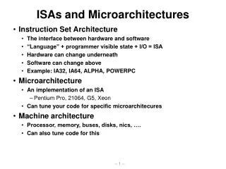
Low Power Design in Microarchitectures and Memories. [Adapted from Mary Jane Irwin ( www.cse.psu.edu/~mji ) www.cse.psu.edu/~cg477. f 0 1 = P 0 1 * f clock. Review: Energy & Power Equations. E = C L V DD 2 P 0 1 + t sc V DD I peak P 0 1 + V DD I leakage

E N D
Low Power Designin Microarchitectures and Memories [Adapted from Mary Jane Irwin ( www.cse.psu.edu/~mji ) www.cse.psu.edu/~cg477
f01 = P01 * fclock Review: Energy & Power Equations E = CL VDD2 P01 + tsc VDD Ipeak P01 + VDD Ileakage P = CL VDD2 f01 + tscVDD Ipeak f01 +VDD Ileakage Dynamic power (~90% today and decreasing relatively) Short-circuit power (~8% today and decreasing absolutely) Leakage power (~2% today and increasing)
D1 D1 S1 S1 S2 D2 S2 D2 Bus Multiplexing • Buses are a significant source of power dissipation due to high switching activities and large capacitive loading • 15% of total power in Alpha 21064 • 30% of total power in Intel 80386 • Share long data buses with time multiplexing (S1 uses even cycles, S2 odd) • But what if data samples are correlated (e.g., sign bits)?
Correlated Data Streams • For a shared (multiplexed) bus advantages of data correlation are lost (bus carries samples from two uncorrelated data streams) • Bus sharing should not be used for positively correlated data streams • Bus sharing may prove advantageous in a negatively correlated data stream (where successive samples switch sign bits) - more random switching Bit switching probabilities LSB MSB Bit position
clk Glitch Reduction by Pipelining • Glitches depend on the logic depth of the circuit - gates deeper in the logic network are more prone to glitching • arrival times of the gate inputs are more spread due to delay imbalances • usually affected more by primary input switching • Reduce logic depth by adding pipeline registers • additional energy used by the clock and pipeline registers Fetch Decode Execute Memory WriteBack pipeline stage isolation register Instruction MAR MDR PC I$ D$
R e g Functional unit clock disable Clock Gating • Most popular method for power reduction of clock signals and functional units • Gate off clock to idle functional units • e.g., floating point units • need logic to generate disable signal • increases complexity of control logic • consumes power • timing critical to avoid clock glitches at OR gate output • additional gate delay on clock signal • gating OR gate can replace a buffer in the clock distribution tree
Clock Gating in a Pipelined Datapath • For idle units (e.g., floating point units in Exec stage, WB stage for instructions with no write back operation) Fetch Decode Execute Memory WriteBack Instruction MAR MDR PC I$ D$ clk No FP No WB
Dynamic Frequency and Voltage Scaling • Intel’s SpeedStep • Hardware that steps down the clock frequency (dynamic frequency scaling – DFS) when the user unplugs from AC power • PLL from 650MHz 500MHz • CPU stalls during SpeedStep adjustment • Transmeta LongRun • Hardware that applies both DFS and DVS (dynamic supply voltage scaling) • 32 levels of VDD from 1.1V to 1.6V • PLL from 200MHz 700MHz in increments of 33MHz • Triggered when CPU load change is detected by software • heavier load ramp up VDD, when stable speed up clock • lighter load slow down clock, when PLL locks onto new rate, ramp down VDD • CPU stalls only during PLL relock (< 20 microsec)
Trigger Mechanism: When do we enable DTM techniques? Initiation Mechanism: How do we enable technique? Response Mechanism: What technique do we enable? Dynamic Thermal Management (DTM)
DTM Trigger Mechanisms • Mechanism: How to deduce temperature? • Direct approach: on-chip temperature sensors • Based on differential voltage change across 2 diodes of different sizes • May require >1 sensor • Hysteresis and delay are problems • Policy: When to begin responding? • Trigger level set too high means higher packaging costs • Trigger level set too low means frequent triggering and loss in performance • Choose trigger level to exploit difference between average and worst case power
DTM Initiation and Response Mechanisms • Operating system or micro architectural control? • Hardware support can reduce performance penalty by 20-30% • Initiation of policy incurs some delay • When using DVS and/or DFS, much of the performance penalty can be attributed to enabling/disabling overhead • Increasing policy delay reduces overhead; smarter initiation techniques would help as well • Thermal window (100Kcycles+) • Larger thermal windows “smooth” short thermal spikes
Trigger Reached Turn Response On Check Temp Check Temp Turn Response Off Initiation Delay Response Delay Policy Delay Shutoff Delay • Initiation Delay – OS interrupt/handler • Response Delay – Invocation time (e.g., adjust clock) • Policy Delay – Number of cycles engaged • Shutoff Delay – Disabling time (e.g., re-adjust clock) DTM Activation and Deactivation Cycle
Designed for cooling capacity without DTM System Cost Savings Designed for cooling capacity with DTM DTM trigger level Temperature DTM/Response Engaged Time DTM Savings Benefits DTM Disabled
Review: Variable VT (ABB) at Run Time • VT = VT0 + (|-2F + VSB| - |-2F|) where VT0 is the threshold voltage at VSB = 0 VSB is the source-bulk (substrate) voltage is the body-effect coefficient • For an n-channel device, the substrate is normally tied to ground • A negative bias causes VT to increase from 0.45V to 0.85V • Adjusting the substrate bias at run time is called adaptive body-biasing (ABB) VT (V) VSB (V)