Download
1 / 16
160 likes | 313 Views
ACS after SM4: New Life for an Old Workhorse David Golimowski Space Telescope Science Institute 22 July 2010. March 2002: ACS installed in HST during Servicing Mission 3B (STS-109) June 2006: Failure of Side 1 LVPS. Switch to redundant Side 2 electronics. All camera operations restored.

E N D
ACS after SM4:New Life for an Old WorkhorseDavid GolimowskiSpace Telescope Science Institute22 July 2010 2010 STScI Calibration Workshop
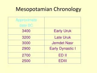
March 2002: ACS installed in HST during Servicing Mission 3B (STS-109) • June 2006: Failure of Side 1 LVPS. Switch to redundant Side 2 electronics. All camera operations restored. • January 2007: Failure of Side 2 LVPS or APB. Loss of WFC and HRC operations; SBC still operational. • May 2009: ACS-R hardware installed during Servicing Mission 4 (STS-125). WFC and SBC pass Aliveness and Functional Tests; HRC not recovered. ACS Chronology STS-125 astronauts Drew Feustel and John Grunsfeld during EVA-3 2010 STScI Calibration Workshop
Four major components of ACS-R: • CCD Electronics Box Replacement (CEB-R) • Low Voltage Power Supply Replacement (LVPS-R) • Power Intercept Element (PIE) • Power Output Element (POE) The ACS Repair (ACS-R) 2010 STScI Calibration Workshop
Main CEB-R features: • Teledyne SIDECAR* ASIC** permits optimization of WFC performance via adjustment of CCD clocks, biases, and pixel transmission timing • Built in oscilloscope mode (O-mode) that allows sensing of analog signal from each output amplifier The CEB-R * System for Image Digitization, Enhancement, Control, and Retrieval ** Application Specific Integrated Circuit 2010 STScI Calibration Workshop
Ground testing: • Verified performance of CEB-R with flight-spare WFC, but not actual flight WFC SITe CCD performance highly variable • Revealed non-ideal transient settling behavior in external preamp Preamp not replaced by ACS-R, so behavior with CEB-R not verifiable • Revealed noise dependence on timing of data transmission from CEB-R to MEB WFC Optimization Campaign (1) On-orbit testing: • To satisfy requirement that WFC perform at least as well as before, CEB-R must accommodate above uncertainties via flexible, programmable settings • Need iterative campaign to optimize CCD read noise, gains, linearity, full well depth, CTE, cross-talk 2010 STScI Calibration Workshop
Strategy: • Perform up to 8 iterations of comprehensive CCD performance tests and exploratory adjustments of bias voltages, clock rails, and data transmission timing via uplinked commands to ASIC • Start with pre-failure default CCD voltages and timing patterns as baseline, then vary appropriate values to investigate specific conditions • Converge to optimal settings; truncate Optimization Campaign if possible • Select default CDS mode (dual-slope integrator or clamp-and-sample) • Modify flight software and assembly code to conform to optimal settings WFC Optimization Campaign (2) 2010 STScI Calibration Workshop
OC began 28 May 2009 with pre-SM4 default (old CEB) voltage & timing settings • Initial performance matched or exceeded projections and expectations. Dark current, CTE, and hot pixels consistent with prolonged radiation exposure. • Dual-slope integrator (DSI) selected as default CDS mode • Gradient of 5-10 DN caused by slow drift of bias reference voltage after readout of each row of pixels. Gradient is stable and removable. • Low level (±1 DN) bias stripes caused by 1/f noise generated by ASIC during bias voltage offset. • OC ended 3 Jun 2009 due to anomaly in WFC2 for non-default VOD. Pre-SM4 default settings adopted for all post-SM4 operations. OC Results 2010 STScI Calibration Workshop
WFC Performance Summary * Projected and problematic values from Gilliland et al. 2008 (TIR ACS 2008-04) . **Signal-dependent shift due to incomplete settling of reference voltage in DSI high-pass filter. Effect can be corrected by software algorithm. 2010 STScI Calibration Workshop
WFC Dark Current History 12 hr anneal 6 hr anneal 6 hr anneal -77 C -77 C -81 C 2010 STScI Calibration Workshop
WFC CTE History • EPER test shows worse than expected CTE degradation (0.99989 vs. 0.99992), but… • Evolution of deferred-charge trails from hot pixels show degradation consistent with expectation • Pre-SM4 correction formulae for WFC and HRC aperture photometry valid for post-SM4 data (Chiaberge ISR 2009-01) • Empirical pixel-based CTE corrections now a reality ! (Next talk by Jay Anderson) 2010 STScI Calibration Workshop
WFC Bias and Dark Frames bias “gradient” (5-10 DN) bias stripes (± 1 DN) Superbias - 1 full anneal cycle (DSI; 34 frames) Superdark - 1/2 anneal cycle (DSI; 24 frames) 2010 STScI Calibration Workshop
Caused by 1/f noise (1 mHz to 1 Hz) in bias reference voltage after CDS (Talks by Bernie Rauscher and Markus Loose) • Appears in both DSI and C&S frames • Stripes vary by ~ 0.75 e–; negligible relative to read noise • Noise is correlated; may affect photometry of the faintest sources • Software developed to mitigate effect (Poster A2 by Norman Grogin) Bias Stripe Effect 2010 STScI Calibration Workshop
Bias Stripe Removal (before) (after) 2010 STScI Calibration Workshop
Gain = 2 e–/DN NGC 4701 (pre-SM4) NGC 6217 (post-SM4) Cross Talk (See poster A3 and ISR ACS 2010-02 by Anatoly Suchkov, et al.) 2010 STScI Calibration Workshop
ACS record after SM4: 1 win (WFC), 1 loss (HRC), 1 tie (SBC) • ACS-R Optimization Campaign showed that WFC read noise, linearity, full-well depth, and cross-talk match or exceed pre-SM4 levels • CTE, hot pixels, dark current have degraded to levels consistent with prolonged exposure to HST’s radiation environment • Bias gradient of 5-10 DN caused by a slow drift of the DSI reference voltage during and after the readout of each row of pixels; stable and removable • Low level (1 DN) bias stripes caused by 1/f noise in bias reference voltage set after CDS stage of signal processing chain; not reproducible from frame to frame • Algorithms for mitigating bias stripes and pixel-to-pixel CTE correction will be available to users very soon; STScI is investigating implementation into calacs. Summary 2010 STScI Calibration Workshop
PI: Ed Cheng (Conceptual Analytics) ACS-R Design and Optimization Teams STScI: George Chapman, Marco Chiaberge, Tyler Desjardins, Tracy Ellis, David Golimowski, Norman Grogin, Pey-Lian Lim, Ray Lucas, Aparna Maybhate, Max Mutchler, Merle Reinhart, Marco Sirianni (ESA/ESTEC), Linda Smith, Anatoly Suchkov, Alan Welty, Tom Wheeler GSFC: Steve Arslanian, Kevin Boyce, Darryl Dye, Olivia Lupie, Kathleen Mil, Barbara Scott, Beverly Serrano, Augustyn Waczynski, Erin Wilson Teledyne: Markus Loose (Markury Scientific), Raphael Ricardo 2010 STScI Calibration Workshop