Download
1 / 64
640 likes | 748 Views
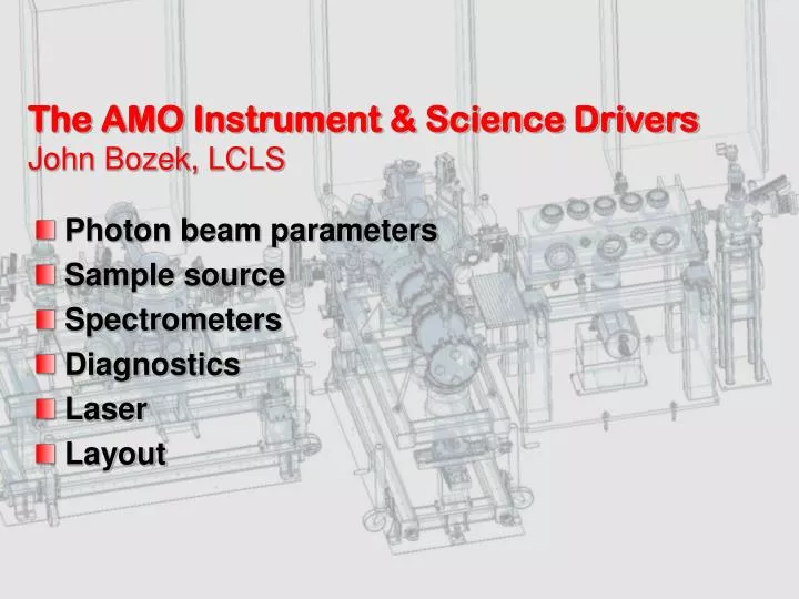
The AMO Instrument & Science Drivers John Bozek, LCLS. Photon beam parameters Sample source Spectrometers Diagnostics Laser Layout. LCLS Soft x-rays: 825 – 2000 eV. Low energy limit is determined by the accelerator design. LCLS Soft x-rays: 825 – 2000 eV.

E N D
The AMO Instrument & Science DriversJohn Bozek, LCLS • Photon beam parameters • Sample source • Spectrometers • Diagnostics • Laser • Layout
LCLS Soft x-rays: 825 – 2000 eV • Low energy limit is determined by the accelerator design
LCLS Soft x-rays: 825 – 2000 eV High energy cut-off by the deflecting optics • 15mrad incidence angle, B4C coating:
AMO studies fundamental interactions • Through years of investigation, we have a pretty good idea what happens when we hit an atom with an x-ray? • Consider Ne atoms and ~1keV photons
Ne 1s photoabsorption Y. Saitoh et al, Spring-8 BL25SU web site http://www.spring8.or.jp/pdf/en/res_fro/98-99/p80-p81.pdf
Scientific Goals of the AMO instrumentation • Investigate multiphoton and high-field x-ray processes in atoms, molecules and clusters • Multi-photon ionization/excitation in atoms/molecules/clusters • Accessible intensity on verge of high-field regime • Study time-resolved phenomena in atoms, molecules and clusters using ultrafast x-rays • Inner-shell side band experiments • Photoionization of aligned molecules • Temporal evolution of state-prepared systems
AMO Instrument – Experimental Facilities • Optics • High Field Physics Chamber • Gas jet • Electron TOFs • Ion spectrometers • X-ray spectrometers • Chamber, shielding, pumping, shutter, etc • Diagnostics Chamber • Magnetic bottle electron spectrometer • Beam screens • Pulse energy monitor • Pulse picker
AMO Instrument Design – focusing optics • Peak intensity depends on size of beam focus – accessible physics depends on intensity • Interaction region ~140m from source • Source @ 825 eV - 116mm • Divergence @ 825eV - 5.7mrad • Unfocussed beam diameter ~1.1mm • Focusing optics ~1m from interaction region
Focusing Optics – Elliptical Bender • Side shaping required to achieve best shape Images courtesy of Alexis Smith & YiDe Chuang, LBNL
Focusing Optics – Elliptical Bender • Optics can be reshaped for 2nd focus 1m downstream with slight increase in slope error Images courtesy of YiDe Chuang, LBNL
Focusing Optics – Surface Coatings • B4C has good reflectivity up to ~ 2000eV and can withstand intense LCLS beam • Also good rejection of higher harmonics • ~10% reflectivity at 2475eV • Five mirrors between source and sample – 66% transmission at 825 eV & 1∙10-5 transmission at 2475
Focusing Optics – Surface Coatings • Regina Soufli @ LLNL has been working on methodology to achieve smooth B4C coatings – slower deposition Increased surface stress, however, which may result in delamination
Focusing Optics – Surface Coatings • Compromise position at 10mTorr sputter pressure 5-7Å roughness but much lower stress in film Roughness of ~10Å does not appreciably decrease reflectivity at 2000eV
O ring Valve plunger Piezo disk translator Electrical feed through Gas supply Experimental station - Gas jet • Pulsed valve – type described by Proch & Trickl, Rev. Sci. Instrum. 60, 713 (1989)
Gas supply XYZ stages Electrical feed through Pulsed valve Experimental station - Gas jet • Pulsed valve assembly
Experimental station – Pulsed Gas Jet Skimmer Gas jet chamber X ray beam Turbo pump Interaction region
Experimental station - Gas jet Multiple skimmers configuration Intermediate chambers Gas jet chamber X ray beam Interaction region Turbo pumps
High Field Physics – Ion Spectrometers • Three different types of Ion Spectrometer • Time-of-flight spectrometer – using integrating metallic anode • Wiley & McLaren, Rev. Sci. Instrum., 26, 1150 (1955). • Velocity map imaging spectrometer – using a phosphor screen to image impact location of ions • Eppink & Parker, Rev. Sci. Instrum., 68, 3477 (1997). • Momentum resolving spectrometer – using a delay line anode to measure position and time of ion impact • Dörner et al., Phys. Rep. 330, 95 (2000).
High Field Physics – Ion Spectrometers • Ion spectrometers are interchangeable via common sized flange • Similar schemes for mounting lenses/meshes & flight tube • Only integrating ion spectrometer will be used in first year
Experimentation station – Ion TOF Magnetic shield Detector 12” flange Acceleration grid Extractor grid Repeller grid • Three different ion detectors/spectrometers: • m/q spectrometer • VMI • Momentum resolving Flight tube Interaction region
High Field Physics – Electron Time-of-Flight • Five spectrometers arranged around interaction region at following angles:
High Field Physics – eTOF • Based on a successful design used by D. Lindle’s group at ALS – designed for up to 5keV electrons • Relatively flat transmission above 20eV KE Figures from O. Hemmers et al., Rev. Sci. Instr., 69, 3809 (1998)
Experimentation station - ETOF Detector Aperture 2 – 2V Lens 2 - -4575V Lens 4 + Flight tube- -5000V IR Aperture 1- 0V Lens 3 - -4850V Lens 1 - -4000V Ground tube 0V
Experimentation station - ETOF Magnetic shielding Detector Electrical lens Actuators
Experimentation station - ETOF Magnetic shielding Turbo pump Electrical lens Actuators
High Field Physics – eTOF • Five electron spectrometers arrayed around interaction region
Experimental station - Magnetic shielding • Mu metal lining • Linked to each spectrometer • Allow pumping • Continuous permeability
Experimental station – Chamber X-Section eTOF Gas jet port Interaction region Ion TOF
High Field Physics – X-ray spectrometers • Two of the electron spectrometers can be removed & replaced with x-ray emission spectrometers • Spectrometers require high efficiency for diffuse gaseous targets • Single shot capable detectors – either CCD’s/CMOS detectors directly or MCP amplified phosphor screen imaged with camera external to vacuum • Two spectrometers – a grating spectrometer for <2 keV and crystal spectrometer for >2 keV • Design not yet complete
High Field Physics – X-ray spectrometers • With guidance from plasma physics and EBIT measurements – concave elliptical crystal spectrometer • Crystals formed by bending them onto a mandrel • Energy ranges for crystals that are easily bent:
High Field Physics – X-ray spectrometers • Geometry described by Henke et al., Rev. Sci. Intr., 54, 1311 (1983). • With h = 25mm & R0 = 600mm
Positioning table • Load capacity: 1000Kg • Ranges of motion: • All 6 degrees • ±50mm in XYZ • ±5º in Pitch, Yaw, Roll • Repeatability ±1µ
Positioning table Motorized stages XY Moving frame Slave stages XY Spherical bearing joints Motorized stages Z Anchored frame 3 x Spherical head feet
AMO Instrument - Diagnostics • Diagnostics in a separate chamber with: • Magnetic bottle spectrometer • Measures photon wavelength and bandwidth • Can also be used to measure temporal overlap of FEL & laser beam • Total pulse energy monitor • Measures pulse energy on each pulse • Two beam screens • Measures position & size of beam • Either geometric or coherent interference based
Diagnostics – Magnetic Bottle • Magnetic field directs electrons to detector increasing collection efficiency • As first described by Kruit & Read, J. Phys. E, 16, 313 (1983)
Diagnostics – Magnetic Bottle • Single shot electron energy spectrum – measure photon energy and bandwidth Design courtesy of Chris Roedig (Lou DiMauro’s group at OSU).
Diagnostics – Beam Viewing Screens • Two screens separated by ~ 1m to measure beam trajectory & divergence • 1st screen partially transparent – 500mm of YAG on SiN membrane imaged with CCD (120Hz) • Second screen can extinguish beam using a thick YAG crystal
5 Tc200 Tc150 Tc100 4 3 2 1 0 0 0.05 0.1 0.15 0.2 0.25 0.3 Time [ms] Total Energy (Thermal) Sensor provides calibrated measurement of FEL pulse energy Measures FEL energy deposition through temperature rise Cu heat sink Thermistors Nd0.66Sr0.33MnO3 (On back of substrate) Sensor Temperature Rise FEL pulse [K] 0.5 mm Si substrate t = 0 t = 0.25 ms t = 0.1 ms Thermal diffusion of FEL energy VG from R. Bionta
Diagnostics chamber – downstream Magnetic bottle Differential pumping Beam profile monitor Power monitor Magnetic bottle magnet XYZ stage Beam viewing screen
Beam Shutter • Upstream of the optics a single pulse beam shutter will be installed in the beamline • The shutter is a commercial product that will be modified with coatings to protect the shutter blade • <2ms open/close time
NEH Laser System and Optical Transport Laser Hall Hutch 3 Hutch 2 Hutch 1 49
Laser Conceptual Design Pulse Stretcher 30 fs Bandwidth Dazzler 30 fs Ti:sapphire Oscillator 800 nm 5 W Nd:YVO4 Multi-Pass Preamplifier 10-30 Hz, <30 mJ Regenerative Amplifier 1kHz, <5 mJ 20W Nd:YLF Pump Laser @ 527nm 1.2 kHz 120mJ Nd:YAG Pump Laser @ 532nm, 120 Hz 300 mJ Nd:YAG Pump Laser @ 532nm 10-30 Hz Pulse Cleaner Optical Transport Harmonics Pulse Compressor (Single Grating) Topaz OPA OR 50
Pulse Stretcher 30 fs Bandwidth 30 fs Mode Locked Ti:sapp @ 800 nm 5 W Nd:YVO4 Regenerative Amplifier 1kHz, <5 mJ 30W Nd:YLF Pump Laser @ 527nm 1.2 kHz Pulse Cleaner Laser Hall Hutch 2 Optical Transport Optical Transport Optical Transport Pulse Compressor (Single Grating) Harmonics Experiment Chambers NEH Laser DIAGNOSTIC SUITE -Spectrometer -Autocorrelator -Frog -Beam Analyzer -Power Meters -Oscilloscopes
Laser Hall Laser Tables Laser Hall Entry 3X, Optical Transport Tubes 12’ 26’ 15’ Regen Amplifier Equipment Racks 5’ Master Oscillator 52
NEH (AMO) Laser Configuration • 120 Hz, 2-3mJ Ti:Sapphire • Oscillator & regen upstairs in laser lab • Vacuum beam transport to hutch • Compressor, color conversion in hutch • Two arms – one to experiment, other to diagnostics by Greg Hays
Introducing Laser into AMO Chamber • Laser introduced on-axis using mirror with hole • All focusing/steering outside vacuum