Download
1 / 24
240 likes | 496 Views
Combinational Circuit – Arithmetic Circuit. Parallel Adder Example: 4-bit adder. Combinational Circuit – Arithmetic Circuit. Cascading Adder Cascade four full adder Classical method: 9 variable input needs 2 9 = 512 line of truth table

E N D
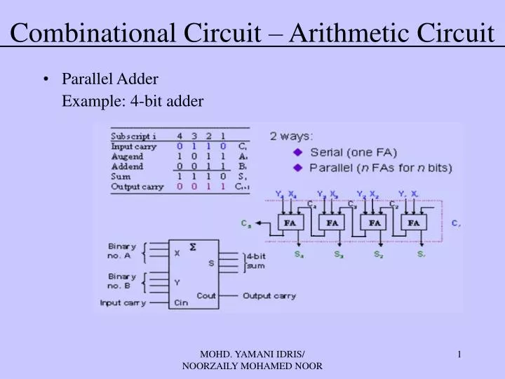
Combinational Circuit – Arithmetic Circuit • Parallel Adder Example: 4-bit adder MOHD. YAMANI IDRIS/ NOORZAILY MOHAMED NOOR
Combinational Circuit – Arithmetic Circuit • Cascading Adder • Cascade four full adder • Classical method: 9 variable input needs 29 = 512 line of truth table • Cascading method can be expanded to greater number. Example: 16-bit parallel adder MOHD. YAMANI IDRIS/ NOORZAILY MOHAMED NOOR
Combinational Circuit – Arithmetic Circuit • Usage: Poling system (for 6 person) • Use full adder and parallel adder 4-bit (binary) • Each full adder can add 3 polls MOHD. YAMANI IDRIS/ NOORZAILY MOHAMED NOOR
Combinational Gates – Arithmetic Circuit • Adder-Subtractor • Use two’s complement X-Y=X+(-Y) • Two’s complement for Y = invert each Y bit and add 1 MOHD. YAMANI IDRIS/ NOORZAILY MOHAMED NOOR
Combinational Gates – Arithmetic Circuit • BCD Adder • Classical method needs 29 lines in TT • As a replacement, we use binary adder with a little alteration MOHD. YAMANI IDRIS/ NOORZAILY MOHAMED NOOR
Combinational Gates – Arithmetic Circuit BCD Adder • Strategy • Use 4-bit parallel adder to ad 2 BCD code • If answer <10, therefore it is correct (just leave it) • If answer ≥10, therefore some calibration is needed to get to correct C, S8, S4, S2 and S1. Repeat this strategy for other 4-bit parallel adder MOHD. YAMANI IDRIS/ NOORZAILY MOHAMED NOOR
Combinational Gates – Arithmetic Circuit • When answer <10, therefore total BCD = total Binary, no calibration is needed • When answer ≥10, therefore Calibration Total BCD = Total Binary + requirement for calibration C=K+Z8.Z4 +Z8.Z2 MOHD. YAMANI IDRIS/ NOORZAILY MOHAMED NOOR
Combinational Gates – Arithmetic Circuit • Comparator • Magnitude comparator: compare two value A and B to ensure if A>B, A=B or A<B • Classical method need 22n line in TT • Explore dissimilarity • How we compare two 4-bit value A(a3 a2 a1 a0) and B(b3 b2 b1 b0) • If (a3>b3) therefore A>B • If (a3<b3) therefore A<B • If (a3=b3) therefore A=B and so on.. MOHD. YAMANI IDRIS/ NOORZAILY MOHAMED NOOR
Combinational Gates – Arithmetic Circuit A3’B3 x3 A3 B3’ A3 B3 A3’B3 + x3A2’B2 + x3x2A1’B1 + x3x2x1A0’B0 A2 x2 B2 (A<B) A1 x1 A3B3’ + x3A2B2’+ x3x2A1B1’+ x3x2x1A0B0’ B1 A0 x0 (A>B) B0 (A=B) x3x2x1x0 MOHD. YAMANI IDRIS/ NOORZAILY MOHAMED NOOR
Combinational Circuit - Arithmetic Circuit • Comparator MOHD. YAMANI IDRIS/ NOORZAILY MOHAMED NOOR
Combinational Circuit – MSI Circuit • There are four useful MSI circuit • Decoder • Demultiplexer • Encoder • Multiplexer • Block Diagram MOHD. YAMANI IDRIS/ NOORZAILY MOHAMED NOOR
Combinational Circuit – MSI Circuit DECODER • Codes used for representing entity, e.g. your name is a code which represent yourself (entity) • This code can be identified (or decoded) using a decoder: Provide code, identify entity • Change binary information from n input line (maximum value for) 2n output line • Is known as line decoder n to m, or n:m or nxm decoder (m<=2n) • Might be used to generate 2n (or less) minterm for n input variable MOHD. YAMANI IDRIS/ NOORZAILY MOHAMED NOOR
Combinational Circuit – MSI Circuit DECODER • Example: if code 00, 0, 10, 11is used to identify four bulbs, therefore we need 2-bit decoder • This is 2x4 decoder which select output line based on the given 2 bit. • Truth table MOHD. YAMANI IDRIS/ NOORZAILY MOHAMED NOOR
Combinational Circuit – MSI Circuit DECODER • From the truth table, decoder circuit 2x4 is • Notes: each output in 2 variable minterm expression (X’Y’, X’Y, XY’, XY) MOHD. YAMANI IDRIS/ NOORZAILY MOHAMED NOOR
Combinational Circuit – MSI Circuit DECODER • Design of 3x8 decoder • Usage? Conversion from binary to octal MOHD. YAMANI IDRIS/ NOORZAILY MOHAMED NOOR
Combinational Circuit – MSI Circuit DECODER • In general: for n-bit code, decoder suppose to select up to 2n line MOHD. YAMANI IDRIS/ NOORZAILY MOHAMED NOOR
Combinational Circuit – MSI Circuit DECODER – Function execution • Boolean function in SOM for can be executed with decoder (to generate minterm) and OR gate (used for forming “sum”) • Any combinational circuit with n input and m output can be done with n:2n decoder and with m OR gate • Good for circuit with a lot of output, and each function is express with several minterm MOHD. YAMANI IDRIS/ NOORZAILY MOHAMED NOOR
Combinational Circuit – MSI Circuit DECODER – Function execution • Example: Full Adder MOHD. YAMANI IDRIS/ NOORZAILY MOHAMED NOOR
Combinational Circuit – MSI Circuit DECODER with Enable • Most decoder has an enable signal, therefore it only active when enable, E=1 • Truth table MOHD. YAMANI IDRIS/ NOORZAILY MOHAMED NOOR
Combinational Circuit – MSI Circuit DECODER with Enable • In MSI, enable signal for decoder is zero enable, E’, therefore this device only active when enable E’=0 MOHD. YAMANI IDRIS/ NOORZAILY MOHAMED NOOR
Combinational Circuit – MSI Circuit LARGE DECODER • Large decoder can be built using small size decoder • E.g. 3:8 decoder can be built using 2:4 (with 1 enable) as the following MOHD. YAMANI IDRIS/ NOORZAILY MOHAMED NOOR
Combinational Circuit – MSI Circuit LARGE DECODER • E.g. 4:16 decoder can be built using two 3:8 decoder (with 1 enable) as the following. • How can you build 4:16 decoder by using 2:4 decoder with enable? MOHD. YAMANI IDRIS/ NOORZAILY MOHAMED NOOR
Combinational Circuit – MSI Circuit ENCODER • Encoder is the inversion of decoder. • Several sets of input line, select one, it produce similar code for selected line • Consist of 2n (or less) input line and n output line • Created from OR gate • Example: MOHD. YAMANI IDRIS/ NOORZAILY MOHAMED NOOR
Combinational Circuit – MSI Circuit Truth table MOHD. YAMANI IDRIS/ NOORZAILY MOHAMED NOOR